Anetic Aid Ltd
QA4 Manual Surgery Trolley Operating Instructions Issue 12 May 2013
Operating Instructions
15 Pages
Preview
Page 1
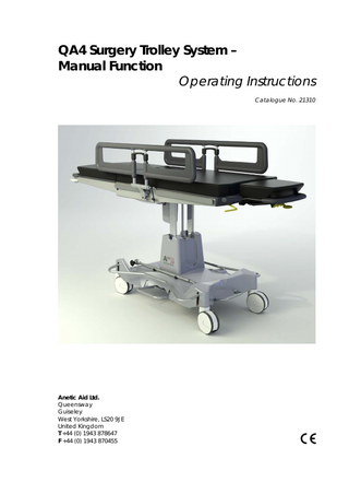
QA4 Surgery Trolley System – Manual Function Operating Instructions Catalogue No. 21310
Anetic Aid Ltd. Queensway Guiseley West Yorkshire, LS20 9JE United Kingdom T +44 (0) 1943 878647 F +44 (0) 1943 870455
QA4 Surgery Trolley System - Manual Function Operating Instructions
Contents
Page
1. Introduction 1.1. Warnings and Cautions 1.2. Scope of Use 1.3. Equipment Classification 2. Product Specifications 3. Product Functions 3.1. Height Adjustment 3.1.1. Problems Raising the Patient Platform 3.1.2. Pump Bleeding Instructions 3.2. Using the Brakes 3.3. Using the Steering Pedal 3.4. Using the Backrest Function 3.5. Using the Trendelenberg Function 3.6. Using the Head Section 3.7. Using the Leg Section 3.7.1. Removing the Leg Section 3.7.2. Replacing the Leg Section 3.7.3. Articulating Leg Section (optional) 3.8. Using the Cotsides 3.8.1. Rotating the Cotsides 3.8.2. Removing the Cotsides 3.8.3. Replacing the Cotsides 3.8.4. Attaching the Full Length Cotside 3.8.5. Rotating the Full Length Cotside 3.9. Using the Transfusion Pole 3.10. ‘C’ Arm Access 4. Patient Weight Limits 5. K8 Pressure Care Mattress 6. Cleaning and Disinfecting the Trolley 7. Product Warranty 8. Product Maintenance 9. Label Identification
1 1 1 1 2 3 4 4 4 4 4 4 4 5 5 5 6 6 6 7 7 7 7 8 8 8 9 9 9 10 10 10
QA4 Surgery Trolley System - Manual Function Operating Instructions
1. Introduction
These instructions are intended to assist you with the operation of the QA4 manual function surgery trolley and it is important that they are read thoroughly before using the equipment. It is also important to check the trolley before use; ensure that all trolley functions operate to their full range of movement and that all detachable components disengage, re-engage and lock correctly. We recommend that the trolley is visually inspected for any loose or damaged parts, foreign bodies caught in the castors, and hydraulic fluid leakage.
1.1. Warnings and Cautions
Various warnings and cautions are made throughout these operating instructions. A WARNING is given when the personal safety of the patient or user may be affected and when disregarding this information could result in injury. A CAUTION is given when special instructions must be followed. Disregarding this information could result in permanent damage being caused to the trolley.
1.2. Scope of Use
This product is intended for use within a surgical environment for the induction, transport, treatment and recovery of patients. Whilst the trolley can be used to transfer patients out of a surgical environment, the trolley has not been designed as a patient transfer trolley, as it has very low ground clearance that may cause problems when traversing uneven ground. CAUTION: The trolley may be damaged by pushing it across rough or uneven ground.
1.3. Equipment Classification
The trolley has been classified as a ‘Class 1' device.
Document No. 992008
Issue 12 15/05/13
Page 1
QA4 Surgery Trolley System - Manual Function Operating Instructions
2. Product Specifications
Fig. 1
Key to Fig. 1 A. B. C. D. E. F. G. H.
Height, MIN Height, MAX Mattress Length Trolley Length, MAX Mattress Width Trolley Width; Side Rail Width Cotside Width Brake Width (Brakes Off) Base Length Mattress Depth Trendelenberg Tilt; Trendelenberg Reverse Trendelenberg Backrest Articulation Head Section Articulation Weight Limits; Trolley Head Section Leg Section Trolley Weight Leg Section Weight Castor Diameter
Document No. 992008
650 mm 1010 mm 2040 mm 2100 mm 600 mm 655 mm 770 mm 835 mm 1055 mm 75 mm 20° 12° 0 - 80° +25/-30° 160 kg 25 kg 50 kg 127 kg 5 kg 150 mm
Issue 12 15/05/13
Page 2
QA4 Surgery Trolley System - Manual Function Operating Instructions
3. Product Functions
Fig. 2 Key to Fig. 2 1. 2. 3. 4. 5. 6. 7. 8. 9. 10. 11. 12.
Raise & Lower Pedals Brake Pedals Steering Pedal Backrest Actuation Lever Trendelenberg Actuation Lever Head Section Tilt Actuation Lever Removable Leg Section Cotsides Pushing Handles Oxygen Cylinder Mounting Trough (Accommodates E & CD Size's) Transfusion Pole ‘V’ Mounting for Suction Canister
Document No. 992008
Issue 12 15/05/13
Page 3
QA4 Surgery Trolley System - Manual Function Operating Instructions
3.1. Height Adjustment
3.2. Using the Brakes
The height of the patient platform is adjusted by using either of the ‘raise and lower pedals’ (no.5, fig.2). Pumping either pedal will raise the patient platform, lifting either pedal will lower the patient platform.
All four castors are braked simultaneously by depressing either of the brake pedals (no.2, fig.2) at any point along the length of the pedal. The brakes are disengaged by lifting either pedal.
WARNING: Ensure there is nothing to impede the raising or lowering of the patient platform as this could result in damage to the equipment and/or injury to the patient.
The trolley can be manoeuvred more easily by engaging the steering (5th wheel) mechanism. The mechanism is engaged by pressing the steering pedal (no.3, fig.2) and disengaged by lifting the pedal.
CAUTION: Ensure that there is no equipment stored in the base of the trolley before lowering the patient platform.
3.1.1. Problems Raising the Patient Platform If the trolley will not ascend, or excessive pumping is required to raise the trolley to its maximum height, the trolley’s pump may need bleeding to remove a build up of air.
3.1.2. Pump Bleeding Instructions Priming
Two People will be required as both the raise & lower pedals need to be operated simultaneously. One person lifts either of the raise & lower pedals & holds it in this position while the second person pumps the other raise & Lower pedal for 20 strokes. Switch Sides and repeat this procedure.
Cycling
Pump either of the 'Raise & Lower' pedals to position the top as high as it will go & continue to pump for a further 10 strokes. Fully lower the trolley and repeat on the same side. Switch sides and repeat the procedure. It may be necessary to repeat these procedures up to three times to fully bleed the pump.
Document No. 992008
Issue 12 15/05/13
3.3. Using the Steering Pedal
CAUTION: Applying the steering pedal with excessive force, i.e. by standing on it, will cause permanent damage to the mechanism. CAUTION: The steering pedal is designed to disengage automatically when the trolley is pushed foot end first over an obstruction. Attempting to prevent this will cause damage to the mechanism. The steering mechanism should be allowed to disengage and then can be reengaged after negotiating the obstruction. CAUTION: The steering pedal must be disengaged manually when the trolley is pushed or pulled head end first over an obstruction, e.g. a lift threshold, or damage may occur.
3.4. Using the Backrest Function
The backrest is moved up or down by pulling up on the backrest actuation lever (no.4, fig.2) whilst keeping a firm grip on the pushing handle (no.10, fig.2) to control the movement. NOTE: It is important to note that the backrest provides only minimal lift assistance; the patient should be assisted into a sitting position and the backrest articulated up.
3.5. Using Function
the
Trendelenberg
The patient platform can be moved into a Trendelenburg or reverse Trendelenburg position by pulling up on the trendelenberg actuation lever (no.5,
Page 4
QA4 Surgery Trolley System - Manual Function Operating Instructions
fig.2) whilst maintaining a firm grip on the pushing handles (no.9, fig.2) to control the movement. CAUTION: When the patient is positioned over the perineal cut out the patient weight is offset towards the foot end of the trolley and the patient platform is no longer evenly balanced. Extra effort will be required to tilt the trolley top into a head down position.
Remove
3.6. Using the Head Section
The head section is moved by pulling up on the head section tilt actuation lever (no.6, fig.2). The head section is also designed to be removed for specific theatre procedures; i.e. gynae and urology, to give greater anaesthetist access to the patient. Removing the head section prior to administering anaesthetic reduces the length of the backrest and the need to reposition the patient in theatre. Removing the head section also gives greater access to the patient from the head end for theatre staff. The head section is removed by lifting the release handle, fig.3, then lowering and removing the head section from the support bracket, fig.4. WARNING: When the head section is fitted on to the trolley, ensure that it is fully engaged and securely locked in position.
Fig. 4
3.7. Using the Leg Section
The trolley is fitted as standard with a non-articulating lightweight leg section (if the trolley is fitted with an articulating leg section refer to section 3.7.3).
3.7.1. Removing the Leg Section
Push
Lower
Push Pull Fig. 5 Lift Fig.3
Document No. 992008
Depress both buttons as shown in fig.5 (one button is located on each side of the trolley) and remove the leg section. WARNING: Ensure that any persons responsible for removing the leg section adopt good posture and stance, in
Issue 12 15/05/13
Page 5
QA4 Surgery Trolley System - Manual Function Operating Instructions
accordance with the relevant ‘Moving and Handling’ policies, to prevent injury to the user.
3.7.2. Replacing the Leg Section
The articulating leg section is moved up and down by pulling up on the leg section actuation lever (no.1, fig.7) whilst keeping a firm grip on the pushing handle (no.2, fig.7) to control movement. To remove the articulating leg section, refer to section 3.7.1. CAUTION: When tilting the trolley into a reverse trendelenberg position ensure the articulating leg section is returned to a horizontal position or damage may occur.
Push Fig. 6 Engage the locating spigots of the leg section as shown in fig.6 and push home firmly until the leg section is fully engaged. WARNING: Ensure that the leg section is fully engaged and securely locked in position.
3.7.3. Articulating Leg Section
Note; the articulating leg section is an optional accessory for this trolley.
NOTE: The articulating leg section should be in the down position to the maximum angle before being removed. This shortens the distance between the end of the leg section and the mounting sockets. This does two things; a) It provides better access to the release buttons, b) It reduces the distance that the user has to reach to support the weight of the articulating leg section. NOTE: When replacing the articulating leg section pull the actuation handle to operate the gas struts and allow the location spigots to achieve a horizontal position.
3.8. Using the Cotsides
The trolley is fitted with four cotsides (no.8, fig.2) that can be individually removed from the trolley or rotated through 180 degrees. Each cotside is mounted into a fixed socket that is labelled with a position number, (1) – (4), this corresponds with the numbered label on the cotside and ensures that each cotside is correctly positioned. See the following sections for more information on rotating, removing and replacing the cotsides.
Fig. 7
Document No. 992008
Issue 12 15/05/13
Page 6
QA4 Surgery Trolley System - Manual Function Operating Instructions
3.8.1. Rotating the Cotsides
Push the button as indicated and rotate the cotside, which will automatically relock in the next position, fig.8.
3.8.3. Replacing the Cotsides
Align the stem of the cotside to the socket and let the cotside drop into position, the cotside will automatically lock in position when replaced. CAUTION: Ensure that the cotsides are located into their respective numbered sockets to prevent the cotsides clashing.
Rotate
3.8.4. Attaching the Full Length Cotside
The optional full length cotside attaches to the trolley by hooking onto the side bar. To secure the cotside, rotate the locking clamp handle 90° in either direction, shown in fig.11 WARNING: Failure to secure the cotside to the side bar using the locking clamp could result in injury to the patient.
Push Fig. 8
3.8.2. Removing the Cotsides
Ensure the cotside is in the ‘up’ position, push the button as indicated and remove the cotside, fig.9. Lift
Fig. 10
Push Fig. 11
Fig. 9 Document No. 992008
Issue 12 15/05/13
Page 7
QA4 Surgery Trolley System - Manual Function Operating Instructions
3.8.5. Rotating the Full Length Cotside
When the cotside is secured to the trolley, shown in fig. 11. Pull the handle in the up direction as indicated in fig.12 and rotate the cotside away from the trolley into the down position. The cotside will automatically relock in the down position.
Fig. 12
3.9. Using the Transfusion Pole
The trolley is fitted with a loose transfusion pole (no.11, fig.2) that can be fitted at any point along the side bar and secured using the locking lever. To adjust the height of the transfusion pole, as illustrated in Fig.16; grasp the locking mechanism (A) and using your thumb, lift the mechanism to release the lock and move the pole up or down to the required height (B); release the mechanism to lock the pole in position.
Fig. 13
3.10. ‘C’ Arm Access
The mattress and patient platform are made from x-ray translucent materials. The areas, and dimensions, of ‘C’ arm access are illustrated in fig. 14.
The transfusion pole is fitted with two spring-loaded hooks that are designed to return to their original upright position when not in use. Swivel one or both hooks outwards (C) to hang the IV bags. NOTE: The maximum weight limit per IV hook is 3kg or 3 litres, and the safe working load for the IV pole is 6kg.
Document No. 992008
Issue 12 15/05/13
Page 8
QA4 Surgery Trolley System - Manual Function Operating Instructions
result in failure of the trolley and injury to the patient and staff.
5. K8 Pressure Care Mattress
Each mattress part is fixed to the patient platform with Velcro®; this enables the mattress sections to be removed from the trolley for cleaning and replacement. NOTE: The mattress parts should be visually inspected for damage on a daily basis. If the outer mattress fabric is torn, then fluids may penetrate and the mattress should be replaced. Do not attempt to repair tears or splits with self adhesive tapes. CAUTION: Ensure that the mattress is correctly orientated on the patient platform with the Velcro® of the mattress aligning with the Velcro® on the patient platform. CAUTION: Ensure that the mattress is centrally positioned across the width of the patient platform otherwise it may prevent the side rail from locking when raised. Fig. 14
4. Patient Weight Limits 1. Main Body; The trolley is designed to accommodate a maximum patient weight of 160kg. Patients should mount the trolley at the centre of the patient platform and their weight kept as evenly distributed as possible whilst on the trolley. 2. Head Section; The head section is designed to take a maximum weight of 25kg. 3. Leg Section; The leg section is designed to take a maximum weight of 50kg. NOTE: The safe working load is the sum of the maximum patient weight, the weight of any accessories attached to the trolley and the weight of the items on or attached to those accessories. WARNING: Exceeding any of the maximum specified weight limits could
Document No. 992008
Issue 12 15/05/13
6. Cleaning and Disinfecting the Trolley
Clean the trolley with warm water and neutral detergent and dry the surfaces thoroughly using a soft cloth. Apply disinfectant by spray or disinfectant wipe, do not soak or immerse the trolley. Suitable disinfectants are: quaternary ammonium compounds, isopropyl alcohol, chlorine bleach 0.5% and phenolics. Following disinfection, wash off the trolley surfaces with clean warm water and dry thoroughly using a soft cloth. NOTE: It is recommended that only CE marked cleaning products are used in the cleaning of this trolley. NOTE: Dilute all disinfectants in accordance with the manufacturer’s guidelines. CAUTION: Disinfectant products are corrosive in nature; failure to properly wash and dry the trolley surfaces could
Page 9
QA4 Surgery Trolley System - Manual Function Operating Instructions
leave a corrosive residue which may cause damage to the trolley.
damaged parts, foreign bodies caught in the castors and hydraulic fluid leakage.
CAUTION: Do not steam clean or jet wash any areas of the trolley.
Because the handset is in constant use it is particularly vulnerable to wear and tear or damage. Before use it is important to inspect the handset to ensure there is no damage to the cable or the buttons; see section 3.1.1., ‘Using the Handset’, for more information.
CAUTION: Do not use concentrated bleaching disinfectant solutions, organic solvents, abrasive powders or expose any part of the trolley to excessive heat.
7. Product Warranty
The product, when new, is guaranteed to be free from defects in materials and workmanship and to perform in accordance with the manufacturer’s specification for a period of one year from the date of purchase from Anetic Aid Ltd or their approved Distributor. Anetic Aid Ltd will repair or replace, at their discretion, any components found to be defective or at variance with the manufacturer’s specification within this time at no cost to the purchaser. The warranty will take effect from the date of purchase, subject to the purchaser registering the product with Anetic Aid to confirm its receipt, installation date and product details. The warranty does not provide cover for breakage or failure due to tampering, misuse, neglect, accidents, modifications or shipping. The warranty is also void if the product is not used in accordance with the manufacturer’s instructions or is repaired during the warranty period by any persons other than Anetic Aid or its appointed agent. No other expressed or implied warranty is given. For details of our extended warranty packages please contact Anetic Aid or your authorised dealer.
Note; the manufacturer recommends that a spare handset is purchased and stored in an accessible location in the event that the handset becomes damaged. CAUTION: In line with the MHRA Device Bulletin DB2006(5), maintenance work should only be conducted by suitably trained personnel following manufacturer’s guidelines.
9. Label Identification
The following list is a description of all the labels used on the trolley; Maximum patient weight limit is 160kg and the trolley safe working load is 200kg. The maximum load for the head section is 25kg and the maximum load for the leg section is 50kg.
Pump the raise and lower pedal to raise the patient platform, lift the raise and lower pedal to lower the patient platform.
8. Product Maintenance
It is recommended that the trolley is serviced on an annual basis in accordance with the manufacturer’s service schedule. Before use, ensure all trolley functions operate to their full range of movement and that all components disengage, reengage and lock correctly. Also visually inspect the trolley for any loose or Document No. 992008
Issue 12 15/05/13
Pull up on the backrest actuation lever to adjust the backrest angle.
Page 10
QA4 Surgery Trolley System - Manual Function Operating Instructions
Depress both leg section release buttons to remove the leg section.
Pull up on the Trendelenburg actuation lever to adjust the patient platform angle.
Depress the brake pedal to brake all four castors.
The screen printed Anetic Aid brand logo with multiple information symbols (reading from left to right); indicates that the mattress is for a QA3 trolley and is manufactured using K8 technology, the mattress is CE marked, refer to the instructions for use (for cleaning etc.), the mattress is x-ray translucent and latex free.
Depress the steering pedal to engage the 5th wheel steering function.
Pull up on the head section tilt actuation lever to articulate the head section.
Indicates that removable.
Document No. 992008
the
leg
section
Issue 12 15/05/13
is
Page 11
NOTES
NOTES