Berchtold Podiatry
Podo-Q Operating Instructions Nov 2015
Operating Instructions
16 Pages
Preview
Page 1
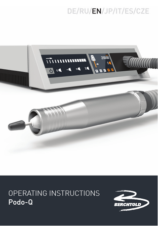
DE/RU/EN/JP/IT/ES/CZE
OPERATING INSTRUCTIONS Podo-Q
Contents
Technical Data
4
Safety Instructions
4
Operation
4
Control Unit
5
Touchpad operation
6
Display operation
7
Changing the dust bag
8-9
Hand piece maintenance and cleaning
10-11
Motor and motor hand piece
12-13
Settings
14
Fault diagnosis control unit
15
Fault diagnosis motor hand piece
16
Technical Data Dimensions W x H x D:
290 x 123 x 250mm
Equipment:
Control unit, micro motor hand piece, dust bag, power cord, instruction manual
Weight:
2300g
Voltage:
95-265V 50/60Hz
Warranty:
24 months 12 months for hand piece
Safety Instructions
•
• • • • •
•
To prevent overheating, at least 30mm clearance must be kept on all sides of the device. The venting slots in the device must not be blocked under any circumstances. Protect the device from moisture The device must not be used to draw liquids Only authorized experts are allowed to open the device Unauthorized opening renders the warranty void The plastic housing must not be cleaned with petrol or chemical detergents. Only use a slightly moistened towel for cleaning. (Unplug device first) Disinfect the surface of the hand piece with a surface disinfectant. Make sure no liquid enters the handpiece.
Operation EN
•
4
•
Press suction cover with dust bag into dust bag compartment. (see pages 8/9) Insert the hand piece cable‘s plug into socket (bracket pointing downwards). Plug the device into a properly installed 95-265 V / 50-60 Hz AC power socket and turn on power switch. (Display lights up)
•
•
•
On the touch sliding strip you can adjust the burr/mandrel rotation to the desired value. Lightly touching the suction level symbols lets you set the suction level (see page 6). The device is put into operation via the start/ stop switch or the switch on the hand piece. Other functions can be operated via the touch pad, as described below. Insert burr/mandrel into hand piece as far as possible. The burr/mandrel in this hand piece is automatically powered as soon as the motor starts. The burr/mandrel may be removed again after the hand piece has come to a stop. Never remove burr/mandel when the device is running to avoid risk of injury! Please do not ever use burrs/ mandrels with damaged or bent shafts! Shaft diameter must be 2.35 mm. Please also mind permissible maximum speeds allowed for the respective burr/mandrel attachment.
Control Unit
Dust bag compartment
Touchpad Display
Hand piece connector socket Fuse
EN 5 IEC connector Power switch
Touchpad
Start/Stop button Hand piece with suction
Suction stop and standby button If pressed for 4 seconds, the device goes to standby mode. Device is automatically put into standby mode if not operated for more than 2 hours. Suction level button low, medium, high EN 6
Slider to adjust burr speed
Display
Burr default and rotation direction indicator small, medium, large and left/right
Burr speed indicator Rotations per minute
Suction strength indicator low, medium, high
EN Rotational direction button left/right Memory buttons Press and hold „Start/Stop“ and press the desired „Memory button“ to save current burr speed, rotational direction and suction level,
7
Dust Bag Changing the dust bag Pull hand piece connector from socket
Remove suction cover and bag
EN 8
Dust Bag
Separate bag from suction cover
Put suction cover on bag and reassemble unit by following these steps in reverse order
EN 9
Maintenance Hand piece maintenance and cleaning Regular hand piece maintenance ensures a secure fit of the burr/mandrel.
• Remove burr/mandrel from hand piece • Unscrew handle sleeve
• Unscrew bearing bushing and pull forward
EN 10
Maintenance
• Press polygon sleeve with burr out of bearing bushing
• Insert burr into collet chuck, thus pulling collet chuck and clamping rollers out of polygon sleeve.
• Clean collet chuck, clamping rollers and polygon sleeve • Assemble following these steps in reverse order
EN 11
Do not use oils or fats
Disassembling the hand piece Removing the micro motor Regular hand piece maintenance ensures a reliable clamping of the burr/mandrel
• Remove burr/mandrel from hand piece • Unscrew handle sleeve
• Unscrew bearing bushing and pull forward
EN 12
Disassembling the hand piece
• Loosen knurled nut by turning left • Caution! Do not turn the plastic lid
Incorrect opening may damage connector pins on the micro motor
• Pull motor with hand piece cover out of motor sleeve
• The motor may now be pulled from the hand piece cover EN 13
Caution: Please mind the micro motor‘s connection pins
Settings Version info menu Pressing the „Suction stop“ button when turning on the device (while the logo is displayed) opens the version info menu. This menu displays information on the software versions and component run times.
VERSIONINFO MAIN PCB TURBINE TOUCH T-H T-B T-L
00001 00001 00000
V1.9H 005 028 013 011 010
Software version control panel Software version turbine Software version touch panel Runtime hand piece Runtime turbine Runtime lamp
User setup menu Pressing the following buttons in the version info menu opens the user setup menu. In the user setup menu, you can set display brightness and the hand piece‘s maximum speed.
USER SETUP BRIGHTNESS RPM-MAX
>080 030
Display brightness Max. Rpm Hand piece (x 1000)
EN 14
Use arrow keys to select the desired setting. Pressing the „SET“ button activates the selected field. When activated (#), setting can be changed using the arrow keys. Pressing „SET“ again saves the setting. To exit version info or user setup menus, restart device using the power switch on the back.
Display Error Analysis Error Symbol
Cause
Solution
Dust bag full
Exchange dust bag and confirm (see page 8/9)
Hand piece not inserted Hand piece faulty
Check plug Replace hand piece motor (see page 13)
Problem with dust suction
Turn device off using the power switch and turn on again. Contact service partner if problem persists.
Hardware error Processor error
Turn device off using the power switch and turn on again. Contact service partner if problem persists.
Dust bag
Hand piece
Suction
Hardware
Fixing smaller issues Error:
Error:
Burrs do not clamp properly:
Burrs do not run smoothly:
Cause:
Cause:
Dirty collet chuck
Bent burr shaft
EN
Solution:
Solution:
15
•
Clean collet chuck & polygon sleeve
•
•
Replace the burr/mandrel
Burr shaft diameter too small
Replace the burr/mandrel
Year
EN 16
Service Date
Date Complete
Service: Canonbury Service Department 7 Arkwright Court Blackpool & Fylde Industrial Estate Blackpool FY4 5DR Service line: 01253 791124 Email: services@canonbury.com 04/11/2015
Canonbury Service Stamp
Sales: Canonbury Products Ltd Warwick House St James Road Brackley NN13 7XY Sales line 01280 706661 Email : info@canonbury.com