bluepoint MEDICAL
CapnoTrue AM Pand CapnoTrue ASP Quick Reference Guide ver 1.0 2012
Quick Reference Guide
2 Pages

Preview
Page 1
Quick Reference Guide
Handheld Mainstream and Sidestream CO2/SpO2 Monitors
CapnoTrue®AMP / CapnoTrue®ASP
Selecting Power Supply External Power Supply
Li-Poly Battery or AA Alkaline Batteries
Connect the power supply cable into the power input socket located at the back of the device.
1. Slide down the cover of the battery compartment on the rear panel.
Only use the power supply Model No. FW 7660M/06 provided with the monitor. The use of a power supply other than this may result in hazardous situation and effect patient’s safety.
2. Insert 4 alkaline batteries (1.5V, AA), ensure the correct orientation in accordance with the polarity markings. 3. Alternatively, insert the rechargeable Li-Poly battery (Model Nr. CT-2500) orientated according to the guiding grooves.
Warnings 1. Zeroing needs to be performed only when an offset in gas values is observed, or when an unspecified accuracy message is displayed. Incorrect zeroing will result in false CO2 gas readings. Refer to chapter 11.4 for detailed information. 2. Do not place the IRMA airway adapter between the endotracheal tube and an elbow as this may allow patient secretions to block the adapter windows and result in incorrect operation. 3. To keep secretions and moisture from pooling on the windows, always position the IRMA CO2 analyzer in a vertical position.
Connecting Sensors Sidestream CO2 Measurement (CapnoTrue ASP)
Mainstream CO2 Measurement (CapnoTrue AMP)
1. Insert the Nomo Adaptor head into the CO2 sidestream inlet port located on the top edge of the CapnoTrue ASP
1. Secure the CO2 analyzer on top of the IRMA airway adapter. It will click into place when correctly seated.
SpO2 Sensor Inspect the SpO2 sensor and connector cables for any external damage. Insert the SpO2 sensor cable into the SpO2 sensor port located on the top edge of the device.
2. Connect a sampling line assembly to the female Luer Lock connection at the Nomo Adapter. A typical sampling line assembly for intubated patients consists of a sampling line and a sidestream airway adapter. For non-intubated patients, a sampling line configuration with nasal and/or oral sampling is typical.
Refer to the sensor ‘Instructions for Use’ to determine if an appropriate sensor is being used, and if it is applied correctly. 2. Connect the 15 mm male connector of the IRMA airway adapter to the breathing circuit Y-piece. 3. Connect the 15 mm female connector of the IRMA airway adapter to the endotracheal tube with or without an angled connector.
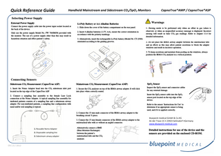
1. Reusable Nomo Adapter 2. Disposable sampling line 3. Sidestream airway adapter
EN 1.0 / 2012
Alternatively connect a HME (Heat Moisture Exchanger) between the patient’s endotracheal tube and the CO2 analyzer.
bluepoint medical GmbH & Co.KG An der Trave 15 • 23923 Selmsdorf •Germany www.bluepoint-medical.com
Detailed instructions for use of the device and the sensors are provided on the enclosed CD-ROM.
Quick Reference Guide
Handheld Mainstream and Sidestream CO2/SpO2 Monitors Symbols and Indicators
Controls and User Interfaces
Menu Overview
a. Pulse waveform (Plethysmogram)
1. SpO2 sensor port
1. Alarm settings
b. SpO2 Functional blood oxygen saturation c. CO2 waveform (Capnogram) d. Expired CO2 gas concentration (EtCO2) e. Battery level indicator f.
Alarm silenced indicator
g. Pulse tone off h. Memory full indicator i.
j.
Home Care mode indicator Limit Alarms are only occur, if the limit is violated for 15seconds continuously Real-Time Mode indicator
k. Neonatal mode indicator Default alarm limits are adjusted to neonatal default settings l.
Current time, displayed in 12h or 24h format
m. Inspired CO2 gas concentration (FiCO2) n. Respiration rate Attention, see user manual for Warnings, Cautions, Notes and additional instructions for use
EN 1.0 / 2012
CapnoTrue®AMP / CapnoTrue®ASP
o. The colour of the bar graph is an indicator for signal quality. p. Pulse rate
2. CO2 measurement port • IRMA CO2 analyzer (AMP) • Nomo Adapter (ASP)
2. Data management 3. Setup
3. USB 2.0 interface 4. Multifunction buttons:
1. Volume
• Scrolling through menu items • Increasing/decreasing parameters • Shortcuts to volume/brightness control
2. Brightness
5. Toggles between various display modes. Shortcut to return to display mode during menu mode
5. Date – Time
6. Silence audible alarm for a max. period of 2min. Optical alarm remains activated. To reset alarms press and hold the button for approx. 3s
7. Language
7. Menu selection. Shortcut to return to the previous menu level during menu mode.
11. Gas compensation
8. On/Off and ENTER button
13. Service
• To turn on the device: press and hold power button briefly. • To turn off the device: press and hold power button for approx. 3s, • Confirms selection 9. Turns pulse tone on/off
3. SPO2 Averaging 4. Neonatal mode
6. CO2 Unit
8. CO2 Scale 9. CO2 Time base 10. Real-Time mode
12. Zeroing
4. Patient ID