Byron Medical Inc
PSI-TEC III Instruction Manual Rev D
Instruction Manual
24 Pages
Preview
Page 1
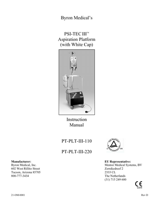
Byron Medical’s PSI-TEC III Aspiration Platform (with White Cap)
Instruction Manual PT-PLT-III-110 PT-PLT-III-220 Manufacturer: Byron Medical, Inc. 602 West Rillito Street Tucson, Arizona 85705 800-777-3434
21-OM-0001
EU Representative: Mentor Medical Systems, BV Zernikedreef 2 2333 CL The Netherlands (31) 715 249 600
Rev D
Table of Contents I.
Introduction
Symbol Definitions
1
Use of this Documentation
2
Warnings and Cautions
2
Operational Safety
2
Modifications
2
Damage or Loss in Shipment
2
Incorrect Items Shipped by Byron Medical
3
Policy on Returned Goods
3
Repair Program
4
Warranty Policy
4
II.
Operation
General Description
5
Operative Controls and Components
5
System Set-up Canisters Set-Up Illustration (See Page 7)
5
Operating Instructions
6
III.
Maintenance
Cleaning Instructions
IV.
8
Troubleshooting
Problems, Causes, and Solutions
9
Appendices A. PSI-TEC III Aspiration Platform Specifications (115V/230V) B. PSI-TEC III Replacement Parts List (115V/230V) C. PSI-TEC III Hand Rail Parts List D. PSI-TEC III Aspiration Platform Schematics (115V/230V)
10 11 19 20
2004 by Byron Medical Byron Medical reserves all rights to this document. No part of this manual may be reproduced, stored, or transmitted in any form or by any means (electronic, mechanical, photocopying, recording, etc.) without prior written permission of Byron Medical. Requests for permission to reproduce or distribute this document should be addressed to:
Byron Medical, Inc., 602 West Rillito Street, Tucson, Arizona 85705
Symbol Definitions Compressed Air
Vacuum
Air Out
Air Return
Type “B” Equipment
Danger: DO NOT use in the presence of flammable anesthetics
AP Attention, Consult users Manual
Risk of Electric Shock. DO NOT remove equipment cover
Footswitch
Fuse and Fuse Rating
21-OM-0001
1 of 21
Rev D
I. Introduction Use of This Documentation This manual provides instruction for operation, maintenance, and troubleshooting procedures. Users should be thoroughly trained in using this product and applicable medical procedures. Instruction manuals should be made available to the user(s) during the procedure. Follow all instructions contained in this manual pertaining to the devices used in the procedure, with particular attention given to the WARNINGS and CAUTIONS. Warnings and Cautions WARNINGS and CAUTIONS statements are placed throughout the text referring to procedures, practices, or conditions considered essential to the safety of personnel and patients and/or equipment and property. All WARNINGS and CAUTIONS should be reviewed prior to the use of this equipment. If you have any questions, please contact Byron Medical, (520) 573-0857 or (800)-777-3434. Operational Safety A thorough review of this entire instruction manual is essential prior to using this product. Byron Medical has taken great care to ensure the safety of the patient and staff. However, features may not be readily discernible without reviewing this documentation. Use of this equipment should therefore not be under taken until the user(s) is fully familiarized with the instructions for assembly and operation. If you have any questions, contact Byron Medical, (520) 573-0857, (800) 777-3434, or FAX (520) 746-1757. Modifications Modifications of any kind NOT recommended and will void all warranties. Damage or Loss in Shipment Thoroughly inspect shipment immediately upon arrival. If goods are received short or in damaged condition, it is important that you notify the transportation company and insist on a notation of the loss or damage on the freight bill. Otherwise, it may be difficult to make a claim against the Transportation Company. If concealed loss or damage is discovered, retain all packaging materials, notify the transportation company immediately, and request an inspection. The agent will make an inspection and grant a concealed damage notation. A concealed damage report must be made within seven (7) days of shipment delivery. After seven (7) days, the transportation company reserves the right to refuse any claim for loss or damage.
21-OM-0001
2 of 21
Rev D
Incorrect Items Shipped by Byron Medical Please check your shipment immediately for any shortage or incorrect items. If any discrepancies exist, notify Byron Medical, (520) 573-0857 or 800-777-3434, at once. Your prompt attention will ensure credit or exchange. ALL DISCREPANCIES BETWEEN THE PACKING LIST AND THE PRODUCTS RECEIVED MUST BE REPORTED WITHIN 48 HOURS OF RECEIPT OF THE PACKAGE TO QUALIFY FOR A CREDIT. Policy on Returned Goods NO RETURNS OR EXCHANGES WILL BE ACCEPTED UNLESS YOU HAVE RECEIVED A RETURN OF GOODS AUTHORIZATION NUMBER (RGA) FROM BYRON MEDICAL. THIS NUMBER MUST BE ON THE RETURN BOX AND ALL WRITTEN COMMUNICATION. Return numbers will expire if items are not returned within 30 days. Credit will only be issued if the merchandise is in saleable condition. If the product has been used in surgery, the product must be CLEANED WITH A DISINFECTANT and a written statement confirming such must accompany the product(s). Full credit will be issued for any item returned in 30 days that is in undamaged and saleable condition. A restocking charge of 25% will be charged to any product returned between 31-90 days. A credit memo, based on the dollar amount, will be issued to the account. OPENED PACKAGES OR BOXES containing disposable items are not returnable for credit or exchange. Each package or sales unit specifically states “Not Returnable if Package Seal is Broken.” NO CREDIT WILL BE ISSUED ON ANY ITEM RETURNED AFTER 90 DAYS. CREDIT MEMOS EXPIRE TWO YEARS AFTER DATE OF ISSUE.
21-OM-0001
3 of 21
Rev D
Repair Program If repairs are necessary due to damage other than that incurred during initial shipment (see section labeled DAMAGE OR LOSS IN SHIPMENT), contact Byron Medical to return your unit. A Return of Goods Authorization number must be obtained from Byron Medical’s Customer Service Department prior to returning any merchandise. When requesting a Return Goods Authorization number, please follow the return policy as listed under the section labeled POLICY ON RETURNED GOODS. Then, please carefully repack and return it post-paid to: Byron Medical, Inc. Attn: Repairs Department RGA #:________________ 602 West Rillito Street Tucson, Arizona 85705 (520) 573-0857 (800) 777-3434 Repairs must be made by Byron Medical or by an approved authorized agent. Attempting repair without prior authorization nullifies all warranties. Warranty Policy Byron Medical products are manufactured for use only by qualified medical personnel who are trained in their use. This equipment carries a one-year warranty against defects from date of sale, which warrants it to be free from defects in material and workmanship. This warranty is valid only to the original purchaser, and will be voided if transferred to a third party. Any Byron Medical product with such defects returned will be promptly repaired or replaced at no charge to the customer. However, you are responsible for the cost of shipping the product to us. The warranty does not apply to damage caused by misuse, mishandling, improper operation, excessive voltage, and/or abuse of the product. Repairs or modifications performed other than by Byron Medical or an approved authorized repair facility will nullify this warranty. For details and warranty information, call Customer Service Department, (520) 573-0857 or (800) 777-3434.
21-OM-0001
4 of 21
Rev D
II.
Operation
General Description The PSI-TEC III Aspiration Platform is a third generation aspiration system with a high flow and powerful vacuum pump designed to evacuate fluid, soft tissue and general tissue removal from a surgical site. It also has a compressor used to drive pneumatic components, all on an integrated cart making it compact, mobile, attachments located at working level, and a pneumatically operated footswitch. Operative Controls and Components 1. Rails (Assembly Required)
1
2. ON/OFF Switches (Vacuum and Air Pumps)
2
3. Vacuum Level Read-out (0-30 in of Hg) 4. Pneumatic Footswitch 3
5
5. Compressed Air (Return/In and Out) System Set-Up
4
1. REMOVE ¾” Button Head Screws (8 each) from unit, and assemble rails to unit.
a. Insert Flat Head Screws (8 each), and tighten screws with enclosed Hex L-Key (See detailed view on page 19).
c. While holding top rail, secure sides with the Female Knobs (2each).
21-OM-0001
b. Attach top rail
d. Using Male Knobs (2 each), tighten IV pole mount to back of railing, and then insert IV bag holder.
5 of 21
Rev D
2. With unit in “OFF” position, attach pneumatic footswitch and power cord to back of unit, and then plug-in power cord to electrical outlet. (Figure 1)
Figure 1
Pneumatic Footswitch
Power Cord
Figure 2
3. Place canister bracket and dual-canister holder with canisters on rail. (Figure 2)
4. Insert IP Canisters liners, and with finger tips push down on liners. (Figure 3) NOTE – Vacuum will not occur in the IP Canister system without BOTH liners installed.
5. Attach disposable filter to connection port turning clock-wise until hand tight. (Figure 4)
Figure 3
Figure 4
Connection Port
6.
Canister Set-Up, see page 5.
7. Remove white cap by turning counter-clockwise . Replace cap by placing it over the (AIR-OUT) port, then turn cap clockwise .
Operating Instructions 1. Switch “ON” aspirator vacuum and compressed air pumps , unit is ready for operation. Depressing the footswitch will activate or deactivate aspirator vacuum (suction) system. NOTE – See INSTRUCTION MANUAL of applicable unit for proper connection and operation of pneumatic components with the PSI-TEC Systems.
21-OM-0001
6 of 21
Rev D
Canister Set-Up Illustration Step 1 Attach disposable filter to connection port turning clock-wise until hand tight. Step 2 Connect filter tubing from disposable filter to port A on CANISTER 2. Step 3 Connect aspirator tubing from port B on CANISTER 2 to port C on CANISTER 1. Step 4 Connect canister tubing E on CANISTER 2 to port D on CANISTER 1. Step 5 Connect other canister tubing G on CANISTER 1 to port F on CANISTER 2. Step 6 Using sterile technique, open tubing package (PT-5558 PSI-TEC); connect one end to port H on CANISTER 1, and other end to the desired cannula instrumentation.
G F
H
E
C B
D
A
Disposable Filter Canister 1 Canister 2
21-OM-0001
7 of 21
Rev D
CAUTION – STOP surgical aspiration PRIOR to removing liners from canisters. WARNING – Single canister usage NOT recommended, as there is a greater probability of filter/ pump contamination. 2. (To CHANGE Filled Liner): a. Switch aspirator vacuum [ full (1500 - 1700cc).
] “OFF” when liner in CANISTER 1 is
b. Disconnect aspiration tubing from port A on CANISTER 1. c. Disconnect canister tubing from port B on CANISTER 2, and then connect it to port A on CANISTER 1. Capping the port prevents waste overflow of liner. Canister LINER Removal A
d. Remove liner, dispose liner and tubing according to your guidelines for HAZARDOUS WASTE DISPOSAL.
B
6. (To REINSTALL New Liner): a. Place new liner in CANISTER 1, and with finger tips push down on lid of liner. Canister 2
Canister 1
b. Connect loose end of canister tubing from CANISTER 1 to port B on CANISTER 2.
c. Reconnect aspiration tubing to port A on CANISTER 1, switch “ON” aspirator vacuum.
III.
Maintenance
Cleaning Instructions The unit exterior should be wiped down with a damp soft cloth and germicide. DO NOT use cleaning solutions containing ALCOHOL or SOLVENTS. WARNING – DO NOT IMMERSE IN LIQUID. STORE COVERED AND IN A CLEAN DRY PLACE. CONTACT PROPER AUTHORIZED PERSONNEL FOR SERVICING. DO NOT autoclave or ETO sterilize aspirator, canisters, liners, or single-use items.
21-OM-0001
8 of 21
Rev D
IV.
Troubleshooting
Problems, Causes, and Solutions Problem No vacuum
Possible Cause Footswitch not activated.
Solution Depress Footswitch.
System not receiving power.
Plug Power Cord into electrical source.
Vacuum Switch [
Push Vacuum Switch [
] “OFF”.
] “ON”.
Footswitch will not control Footswitch not connected to Connect footswitch to unit (rear). aspirator. unit. System will not turn “ON”.
Power cord not plugged-in to Plug-in power cord to electrical electrical outlet. outlet. Fuses blown on back of unit Unplug power cord, replace tripped located just above blown fuse, reconnect power power cord (female connector) cord, switch on vacuum, and depress footswitch.
Low vacuum.
IP Canister Liner(s) properly sealed.
not With vacuum [ ] “ON’ gently push down on lid.
Tubing improperly connected.
Check all tubing at connection points for proper seal.
Aspirator stalls after quick Aspiration pumps still under Release vacuum by venting with restart. load (vacuum). air (remove cannula from patient and restart). No Compression
Pneumatic component inoperative.
System not receiving power.
Plug Power Cord into electrical source
Air Switch [ ] “OFF”.
Push Air Switch [
is Pneumatic component is improperly connected to aspiration compressed air [ ] fittings.
] “ON”.
Ensure pneumatic component is properly connected. Check for visible damage to connectors and tubing.
If still inoperative, Contact Byron Medical, (800) 777-3434 or (520) 573-0857 for technical support.
21-OM-0001
9 of 21
Rev D
APPENDIX - A PSI-TEC III Aspiration Platform Specifications
Size Weight Power Cord AC Power Input Fuse Maximum Vacuum Maximum Flow Rate Sound Level Pump Type(s) Maximum Compressor Air Pressure Internal Pressure Tank Capacity IEC Classification
PSI-TEC III ASPIRATION PLATFORM 115V
PSI-TEC III ASPIRATION PLATFORM 230V
20.18 in (H) x 22.96 in (D) x 18.32 in (W) 51.26 cm (H)x 58.32 cm (D) x 46.53 cm (W)
20.18 in (H) x 22.96 in (D) x 18.32 in (W) 51.26 cm (H) x 58.32 cm (D) x 46.53 cm (W)
80 lbs. / 36.288 Kilograms 10 ft / 3 m Hospital Grade IEC 115 VAC, 60 Hz, 7.5 A T 15 A 250 V 28 in of Hg. / 711 mm of Hg 4.75 CFM (Cubic feet per minute) 52 dB Typical Two cylinder Piston/Single Piston 29 inHg 736.6 mmHg 100 psi MAX compressor output Regulated to 60 PSI 250 psi Minimum (250% Max Compressor Capacity) Class 1 Type B
80 lbs. / 36.288 Kilograms 10 ft / 3 m Hospital Grade IEC 230 VAC, 50 Hz, 3.1 A T 6.3 A 250V 28 in of Hg. / 711 mm of Hg 4.75 CFM (Cubic feet per minute) 52 dB Typical Two cylinder Piston/Single Piston 29 inHg 736.6 mmHg 100 psi MAX compressor output Regulated to 60 PSI 250 psi Minimum (250% Max Compressor Capacity) Class 1 Type B
10 deg to 40 deg C 54 deg to 104 deg F -30 deg to 50 deg C -22 deg to 122 deg F 30% to 75% relative humidity (non-condensing)
10 deg to 40 deg C 54 deg to 104 deg F -30 deg to 50 deg C -22 deg to 122 deg F 30% to 75% relative humidity (non-condensing)
Environmental Operating Temperature Storage/Shipping Temperature Operating Humidity
21-OM-0001
10 of 21
Rev D
APPENDIX - B
PSI-TEC III 115V Platform MODEL: PT-PLT-III-110 PARTS LIST DESCRIPTION
CMI NBR 2196 TIE, CABLE 4" 2520 SCREW, 4-40 X ¼ “ BUTTON HD MACHINE SLOTTED 2552 SCREW, 6-32 X ½ " PHILLIPS PAN HEAD MACHINE 2605 HEX NUT, 6-32 X ¼ " WIDTH 2620 HEX NUT, 8-32 X 11⁄32 " 2625 HEX NUT, 10-32 X 3⁄8 " WIDTH 2665 LOCK WASHER, #6 INTERNAL TOOTH 2675 LOCK WASHER, #8 EXTERNAL TOOTH 2690 LOCKWASHER, 10 INTERNAL TOOTH 2695 LOCK WASHER, #10 SPLIT 3126 NON-INSULATED TERMINAL ¼ " HOLE 4772 TIE-DOWN, FASTRAP 6112 ADHESIVE 10176 FAN, 4” 110V MUFFIN 17060 TUBING, 3⁄16 " SHRINK BLACK 17217 LOCK WASHER, #6 SPLIT 19771 PIPE JOINT COMPOUND 19861 POLY BAG, 6” X 9” 19974 POWER CORD, 125V 10A TO IEC 30400 BAG, CLEAR Z-LOCK 0.004M 12” X12” 32029 RECEPTACLE, 3 PIN 32030 PLUG, 3 PIN 32031 MALE TERMINAL PIN 32032 FEMALE TERMINAL PIN 32345 COMPRESSOR SIDE MTG BRKT(LH/RH) 32346 COMPRESSOR BASE PLATE PSI-TEC III 32347 VACUUM PUMP MTG PLATE (RH+LH) 32348 VACUUM PUMP MOTOR MOUNT 32351 AIR RECEIVER END CAP 32352 AIR RECEIVER TIE ROD 32353 AIR RECEIVER CYLINDER WALL 32357 RADIATOR BRACKET (RH + LH) 32361 ½ "-13 HEX NUT ZINC 32362 ¼ " LOCKWASHER ZINC 32364 3⁄8 " LOCKWASHER ZINC 32365 ½ " LOCKWASHER ZINC 32367 ⅜ “ – 16 X ½ “ BUTTON HEAD SKT CAP 32379 BRONZE MUFFLER 1⁄8 " 32388 ¼ " X 1⁄8 " ADAPTOR 32393 GAST VACUUM PUMP
21-OM-0001
11 of 21
UOM EA EA EA EA EA EA EA EA EA EA EA EA OZ EA IN EA OZ EA EA EA EA EA EA EA EA EA EA EA EA EA EA EA EA EA EA EA EA EA EA EA
Qty 27 1 6 2 4 10 5 9 10 3 3 4 0.20 1 12 2 0.60 1 1 1 4 4 20 20 2 1 2 1 2 4 1 2 4 26 4 4 4 1 1 1
Rev D
PSI-TEC III 115V Platform (Continued) MODEL: PT-PLT-III-110 PARTS LIST CMI NBR DESCRIPTION 32394 GAST COMPRESSOR PSI-TEC III 32395 AIR LOGIC PRESSURE SWITCH 32396 RADIATOR 6” X 6” 32397 120 VAC - HUMPHREY ¼ " VALVE 32399 ¼ " NPT FEMALE CHECK VALVE 32401 KOBY MUFFLER 32402 SIDE ISOLATOR 32403 BOTTOM ISOLATOR 32404 RELAY R14-11A10-120 32411 SWITCH, AIR ACTIVATED 32413 MOLEX 12 PIN FEMALE 32414 SHELL 12 PIN MALE 32415 CASTER, 4" PLATE MOUNT 32416 CASTER,LOCKING 4" PLATE MOUNT 32417 PSI-TEC III U SHAPED BAR 32420 IV POLE MOUNT 32430 MALE 1⁄8 “- ¼ “ MALE ELBOW 32431 FLEX HOSE 32432 SCREW, 10-32 X ½ " BUTTON HEAD CAP 32434 ¼ " BRONZE MUFFLER 32435 MALE ¼ " - MALE ¼ " ELBOW 32437 MALE ¼ " - FEMALE 1⁄8 " ADAPTOR 32438 ¼ " - ½ " MALE ELBOW 32439 1⁄8 " - 1⁄16 " RIGHT ANGLE ADAPTOR 32442 2 FOOT. FLEX HOSE WITH ½ " FEMALE 32446 BASE PLATE, PSI-TEC III 32448 SWITCH, 16 AMP LIGHTED ROCKER 32449 CONN MOLEX BLADE CRIMP 32450 TEE ¼ “ – ⅜ “ COMPRESSION 32451 3⁄8 " STAINLESS STEEL TUBE 41” X 6 32453 3⁄8 " COMP UNION 32454 ¼ " - ¼ " MALE TO MALE COUPLER 32455 RELAY MTG BLOCK WITH RETAINER 32456 TERMINAL,FORKED CRIMP #8 32457 GREEN/YELLOW 16 GAUGE WIRE 32458 BLUE 16 GAUGE WIRE 32459 BROWN 16 GAUGE WIRE 32460 FAN BRACKET 32462 SIDE SUPPORT 32465 VACUUM GAUGE 2 ½ " DIAMETER 32466 1⁄8 “ ID TUBING 32468 AIR OUTLET CONNECTOR
21-OM-0001
12 of 21
UOM EA EA EA EA EA EA EA EA EA EA EA EA EA EA EA EA EA FT EA EA EA EA EA EA EA EA EA EA EA EA EA EA EA EA FT FT FT EA EA EA IN EA
Qty 1 1 1 1 1 1 4 8 2 1 1 1 2 2 1 1 1 1 11 1 1 1 1 1 1 1 2 19 1 1 1 2 2 16 6.25 19.17 32.75 1 3 1 35 1
Rev D
PSI-TEC III 115V Platform (Continued) MODEL: PT-PLT-III-110 PARTS LIST CMI NBR DESCRIPTION 32471 ½ " COMPRESSION TO ¼ " NPT 32472 ¼ "- ¼ " BULK HEAD ADAPTOR 32476 IV POLE 32477 POWER ENTRY MODULE 110-220V 10A 32478 SCREW, ¼ "-20 X ¾ " SOCKET HEAD CAP 32481 FUSE, 15AMP FAST ACTING 32483 SCREW, ¼ "-20 X ½ " SOCKET HEAD CAP 32485 SCREW, 8-32 X 3⁄8 " PAN HEAD PHILLIPS 32486 O-RING 32487 SCREW, 5⁄16 "-18 X 1" BUTTON HEAD 32488 LOCKWASHER, 5⁄16 " ZINC 32489 NUT, 5⁄16 "-18 ZINC 32490 ADAPTOR, GAUGE VACUUM 32491 PLUG, 1⁄8 " HEX PIPE 32493 1⁄8 " QUICK RELEASE TO 3⁄8 " NPT 32494 1⁄8 " QUICK RELEASE TO 10-32 32495 TUBING, 1⁄8 " ID X ¼ " OD SUPER THIN 32497 CLIP,RELAY RETENTION FOR #32404 32502 ATO MUFFLER, ¼ “ MALE 32507 FILTER, DUAL STAGE 32527 MACHINE SCREW, 8-32 X 5⁄8 " TRUS 32541 FOOTSWITCH 32542 1 ¼ " FLUTED PL KNOB 32543 1 ¼ " KNOB WITH STUD 32546 SCREW, 8-32 X ¾ “FLATHEAD 32555 CONNECTOR, 16 AWG 1.187 BLADE CRIMP 32556 COUPLER, 3⁄8 “ TUBING TO 1⁄8 “ BARB 32566 LUG, SOLDER #6 FLAT LOCKING 32567 TUBING, 3⁄8 “ SPLIT LOOM 32568 SHIPPING MATERIALS,PSI-TEC III 32588 PSI-TEC III SIDE RAIL 32589 PSI-TEC III BACK RAIL 32591 5⁄32 " HEX WRENCH, SHORT 32595 3” X 4” PLASTIC BAG 32599 SAFETY RELIEF VALVE, 100 PSI ¼ “ NPT 32600 AIR OUTLET SAFETY COVER 32602 CHAIN, #6 BALL STAINLESS 32603 CLIP, #6 BALL CHAIN STAINLESS 32605 TEE, ¼ “ NPT TO DUAL ¼ “ NPT FEMALE 32606 SCREW, 10-32 X 5⁄8 “ BUTTON HEAD MACHINE SLOTTED 32607 FUSE DRAWER, POWER INLET 32614 LOCKNUT, ¼ “-20
21-OM-0001
13 of 21
UOM EA EA EA EA EA EA EA EA EA EA EA EA EA EA EA EA FT EA EA EA EA EA EA EA EA EA EA EA FT EA EA EA EA EA EA EA FT EA EA EA EA EA
Qty 1 2 1 1 6 2 28 2 2 4 8 4 1 2 1 1 3.25 2 1 1 3 1 2 3 4 2 1 1 3 1 2 1 1 1 1 1 0.25 2 1 2 1 12
Rev D
PSI-TEC III 115V Platform (Continued) MODEL: PT-PLT-III-110 PARTS LIST DESCRIPTION
CMI NBR 32615 LOCKNUT, 3⁄8 “-16 32616 LOCKNUT, ½ “-13 32628 TY-RAP, 30 NYLON 32644 ¼ “-20 X 1” FLATHEAD COUNTER SINK 32666 PSI-TEC III SHIPPING CONTAINER 32680 ENCLOSURE, PLATFORM ALUMINUM 32682 PENETROX ANTI-OXIDANT 32694 SCREW, 6-32 X 5⁄8 “ FLAT HEAD MACHINE SCREW PHILLIPS 32695 SCREW, 8-32 X ½ ” PAN HEAD WITH WASHER 32696 SCREW, 7⁄16 “-14 X 1 ½ ” STAINLESS 32697 LOCKWASHER, 7⁄16 “ SPLIT 32698 HOSE, 7⁄16 “ ID RUBBER 32710 5⁄16 “- ¼ “ QUICK CONNECTOR COUPLING 32714 PSI-TEC III BACK PANEL
21-OM-0001
14 of 21
UOM EA EA EA EA EA EA OZ EA EA EA EA FT EA EA
Qty 4 4 1 8 1 1 0.50 2 10 1 1 0.10 1 1
Rev D
APPENDIX – B (Continued)
PSI-TEC III 230V Platform MODEL: PT-PLT-III-220 PARTS LIST DESCRIPTION
CMI NBR 2196 TIE, CABLE 4" 2520 SCREW, 4-40 X ¼ “ BUTTON HD MACHINE SLOTTED 2552 SCREW, 6-32 X ½ " PHILLIPS PAN HEAD MACHINE 2605 HEX NUT, 6-32 X ¼ " WIDTH 2620 HEX NUT, 8-32 X 11⁄32 " 2625 HEX NUT, 10-32 X 3⁄8 " WIDTH 2665 LOCK WASHER, #6 INTERNAL TOOTH 2675 LOCK WASHER, #8 EXTERNAL TOOTH 2690 LOCKWASHER, 10 INTERNAL TOOTH 2695 LOCK WASHER, #10 SPLIT 3126 NON-INSULATED TERMINAL ¼ " HOLE 4772 TIE-DOWN, FASTRAP 6112 ADHESIVE 17060 TUBING, 3⁄16 " SHRINK BLACK 17217 LOCK WASHER, #6 SPLIT 19771 PIPE JOINT COMPOUND 19861 POLY BAG, 6” X 9” 30400 BAG, CLEAR Z-LOCK 0.004M 12” X12” 32029 RECEPTACLE, 3 PIN 32030 PLUG, 3 PIN 32031 MALE TERMINAL PIN 32032 FEMALE TERMINAL PIN 32345 COMPRESSOR SIDE MTG BRKT(LH/RH) 32346 COMPRESSOR BASE PLATE PSI-TEC III 32347 VACUUM PUMP MTG PLATE (RH+LH) 32348 VACUUM PUMP MOTOR MOUNT 32351 AIR RECEIVER END CAP 32352 AIR RECEIVER TIE ROD 32353 AIR RECEIVER CYLINDER WALL 32357 RADIATOR BRACKET (RH + LH) 32361 ½ "-13 HEX NUT ZINC 32362 ¼ " LOCKWASHER ZINC 32364 3⁄8 " LOCKWASHER ZINC 32365 ½ " LOCKWASHER ZINC 32367 ⅜ “ – 16 X ½ “ BUTTON HEAD SKT CAP 32379 BRONZE MUFFLER 1⁄8 " 32388 ¼ " X 1⁄8 " ADAPTOR 32395 AIR LOGIC PRESSURE SWITCH 32396 RADIATOR 6” X 6” 32397 120 VAC - HUMPHREY ¼ " VALVE
21-OM-0001
15 of 21
UOM EA EA EA EA EA EA EA EA EA EA EA EA OZ IN EA OZ EA EA EA EA EA EA EA EA EA EA EA EA EA EA EA EA EA EA EA EA EA EA EA EA
Qty 27 1 6 2 4 10 5 9 10 3 3 4 0.20 12 2 0.60 1 1 4 4 20 20 2 1 2 1 2 4 1 2 4 26 4 4 4 1 1 1 1 1
Rev D
PSI-TEC III 230V Platform(Continued) MODEL: PT-PLT-III-220 PARTS LIST CMI NBR DESCRIPTION 32399 ¼ " NPT FEMALE CHECK VALVE 32401 KOBY MUFFLER 32402 SIDE ISOLATOR 32403 BOTTOM ISOLATOR 32411 SWITCH, AIR ACTIVATED 32413 MOLEX 12 PIN FEMALE 32414 SHELL 12 PIN MALE 32415 CASTER, 4" PLATE MOUNT 32416 CASTER,LOCKING 4" PLATE MOUNT 32417 PSI-TEC III U SHAPED BAR 32420 IV POLE MOUNT 32430 MALE 1⁄8 “- ¼ “ MALE ELBOW 32431 FLEX HOSE 32432 SCREW, 10-32 X ½ " BUTTON HEAD CAP 32434 ¼ " BRONZE MUFFLER 32435 MALE ¼ " - MALE ¼ " ELBOW 32437 MALE ¼ " - FEMALE 1⁄8 " ADAPTOR 32438 ¼ " - ½ " MALE ELBOW 32439 1⁄8 " - 1⁄16 " RIGHT ANGLE ADAPTOR 32442 2 FOOT. FLEX HOSE WITH ½ " FEMALE 32446 BASE PLATE, PSI-TEC III 32448 SWITCH, 16 AMP LIGHTED ROCKER 32449 CONN MOLEX BLADE CRIMP 32450 TEE ¼ “ – ⅜ “ COMPRESSION 32451 3⁄8 " STAINLESS STEEL TUBE 41” X 6 32453 3⁄8 " COMP UNION 32454 ¼ " - ¼ " MALE TO MALE COUPLER 32455 RELAY MTG BLOCK WITH RETAINER 32456 TERMINAL,FORKED CRIMP #8 32457 GREEN/YELLOW 16 GAUGE WIRE 32458 BLUE 16 GAUGE WIRE 32459 BROWN 16 GAUGE WIRE 32460 FAN BRACKET 32462 SIDE SUPPORT 32465 VACUUM GAUGE 2 ½ " DIAMETER 32466 1⁄8 “ ID TUBING 32468 AIR OUTLET CONNECTOR 32471 ½ " COMPRESSION TO ¼ " NPT 32472 ¼ "- ¼ " BULK HEAD ADAPTOR 32476 IV POLE 32477 POWER ENTRY MODULE 110-220V 10A 32478 SCREW, ¼ "-20 X ¾ " SOCKET HEAD CAP
21-OM-0001
16 of 21
UOM EA EA EA EA EA EA EA EA EA EA EA EA FT EA EA EA EA EA EA EA EA EA EA EA EA EA EA EA EA FT FT FT EA EA EA IN EA EA EA EA EA EA
Qty 1 1 4 8 1 1 1 2 2 1 1 1 1 11 1 1 1 1 1 1 1 2 19 1 1 1 2 2 16 6.25 19.17 32.75 1 3 1 35 1 1 2 1 1 6
Rev D
PSI-TEC III 230V Platform(Continued) MODEL: PT-PLT-III-220 PARTS LIST CMI NBR DESCRIPTION 32483 SCREW, ¼ "-20 X ½ " SOCKET HEAD CAP 32485 SCREW, 8-32 X 3⁄8 " PAN HEAD PHILLIPS 32486 O-RING 32487 SCREW, 5⁄16 "-18 X 1" BUTTON HEAD 32488 LOCKWASHER, 5⁄16 " ZINC 32489 NUT, 5⁄16 "-18 ZINC 32490 ADAPTOR, GAUGE VACUUM 32491 PLUG, 1⁄8 " HEX PIPE 32493 1⁄8 " QUICK RELEASE TO 3⁄8 " NPT 32494 1⁄8 " QUICK RELEASE TO 10-32 32495 TUBING, 1⁄8 " ID X ¼ " OD SUPER THIN 32497 CLIP,RELAY RETENTION FOR #32404 32498 VALVE, 320 ¼ “ FOR 240 VAC 32499 VALVE, 310 1⁄8 “ FOR 220 VAC 32500 RELAY, R14-11A10-10-240 32502 ATO MUFFLER, ¼ “ MALE 32504 COMPRESSOR, 230 VOLT GAST 32505 PUMP, 230 VOLT VACUUM GAST 32506 FAN, 4” 220/230V MUFFIN 32507 FILTER, DUAL STAGE 32527 MACHINE SCREW, 8-32 X 5⁄8 " TRUS 32541 FOOTSWITCH 32542 1 ¼ " FLUTED PL KNOB 32543 1 ¼ " KNOB WITH STUD 32546 SCREW, 8-32 X ¾ “FLATHEAD 32555 CONNECTOR, 16 AWG 1.187 BLADE CRIMP 32556 COUPLER, 3⁄8 “ TUBING TO 1⁄8 “ BARB 32566 LUG, SOLDER #6 FLAT LOCKING 32567 TUBING, 3⁄8 “ SPLIT LOOM 32568 SHIPPING MATERIALS,PSI-TEC III 32588 PSI-TEC III SIDE RAIL 32589 PSI-TEC III BACK RAIL 32591 5⁄32 " HEX WRENCH, SHORT 32595 3” X 4” PLASTIC BAG 32596 POWER CORD, 250V 10A EUROPEAN 32599 SAFETY RELIEF VALVE, 100 PSI ¼ “ NPT 32600 AIR OUTLET SAFETY COVER 32602 CHAIN, #6 BALL STAINLESS 32603 CLIP, #6 BALL CHAIN STAINLESS 32605 TEE, ¼ “ NPT TO DUAL ¼ “ NPT FEMALE 32606 SCREW, 10-32 X 5⁄8 “ BUTTON HEAD MACHINE SLOTTED 32607 FUSE DRAWER, POWER INLET
21-OM-0001
17 of 21
UOM EA EA EA EA EA EA EA EA EA EA FT EA EA EA EA EA EA EA EA EA EA EA EA EA EA EA EA EA FT EA EA EA EA EA EA EA EA FT EA EA EA EA
Qty 28 2 2 4 8 4 1 2 1 1 3.25 2 1 1 2 1 1 1 1 1 3 1 2 3 4 2 1 1 3 1 2 1 1 1 1 1 1 0.25 2 1 2 1
Rev D
PSI-TEC III 230V Platform(Continued) MODEL: PT-PLT-III-220 PARTS LIST DESCRIPTION
CMI NBR 32614 LOCKNUT, ¼ “-20 32615 LOCKNUT, 3⁄8 “-16 32616 LOCKNUT, ½ “-13 32625 FUSE 6.3A 250V SLOW-BLOW GLOW 32628 TY-RAP, 30 NYLON 32644 ¼ “-20 X 1” FLATHEAD COUNTER SINK 32666 PSI-TEC III SHIPPING CONTAINER 32680 ENCLOSURE, PLATFORM ALUMINUM 32682 PENETROX ANTI-OXIDANT 32694 SCREW, 6-32 X 5⁄8 “ FLAT HEAD MACHINE SCREW PHILLIPS 32695 SCREW, 8-32 X ½ ” PAN HEAD WITH WASHER 32696 SCREW, 7⁄16 “-14 X 1 ½ ” STAINLESS 32697 LOCKWASHER, 7⁄16 “ SPLIT 32698 HOSE, 7⁄16 “ ID RUBBER 32710 5⁄16 “- ¼ “ QUICK CONNECTOR COUPLING 32714 PSI-TEC III BACK PANEL
21-OM-0001
18 of 21
UOM EA EA EA EA EA EA EA EA OZ EA EA EA EA FT EA EA
Qty 12 4 4 2 1 8 1 1 0.50 2 10 1 1 0.10 1 1
Rev D