Hardware Guide
98 Pages
Preview
Page 1
DRX
EVOLUTION
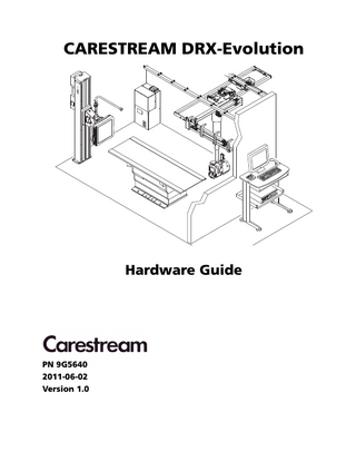
CARESTREAM DRX-Evolution
0HC
Hardware Guide
PN 9G5640 2011-06-02 Version 1.0
Table of Contents 1 Components and Operation Manual Conventions...1-1 Digital Radiography...1-1 Indications for Use...1-1 Usability ...1-2 Training ...1-2 Safe Operation Precautions ...1-3 Emergency Stop Buttons...1-4 CARESTREAM DRX-Evolution ...1-5 Environmental Requirements ...1-6 Acoustic Noise Emission...1-6 Operator Console...1-7 X-ray Generator...1-8 Power Distribution Unit (PDU) ...1-9 Elevating Table with Removable Detector ...1-9 Adjusting the Positions of the Table and the Bucky...1-10 Elevating Base ...1-12 Tabletop...1-13 Telescopic Covers ...1-13 Optional Table Accessories ...1-13 Hand Grips (optional) ...1-14 Remote Table Positioning Control (optional)...1-15 Compression Strap (optional)...1-16 Using the Lockdown Clamps...1-17 24 x 30 CR Cassette Adapter (optional)...1-18 Fixed 43 x 43 Detector Elevating Table (optional) ...1-22 Adjusting the Positions of the Table and the Bucky...1-23 Overhead Tube Crane (OTC)...1-24 X-ray Tube Specifications ...1-24 Power ...1-24 Overhead Tube Crane...1-25 Motion ...1-26 Brake Releases...1-26
i
Collimator Controls ...1-28 Collimator Filtration Information ...1-29 X-ray Beam Axis ...1-30 SID Calculation ...1-30 Dose Area Product Meter (optional)...1-30 DRX-Evolution Wall Stand Portfolio...1-31 Full-Featured Wall Stand (Model VX3733-FFWS)...1-32 Maximum Patient Weight...1-33 Power ...1-33 Full-Featured Wall Stand Components ...1-33 Full-Featured Wall Stand Motion ...1-34 Extending the Full-Featured Wall Stand ...1-35 Full-Featured Wall Stand Bucky...1-36 CARESTREAM Motorized Wall Stand (Model VX3733-CWS)...1-39 Motorized Wall Stand Range of Motion...1-40 Maximum Weight on Horizontal Bucky ...1-40 Using the Motorized Wall Stand...1-41 Moving the Wall Stand...1-41 Motorized Wall Stand Angulation...1-42 Fixed 43 x 43 Detector Wall Stand (optional) ...1-43 Using the Fixed 43 x 43 Detector Wall Stand ...1-43 Non-Motorized Wall Stand (Model VX3733-CWS-B)...1-44 Non-Motorized Wall Stand Range of Motion ...1-45 Maximum Weight on Horizontal Bucky ...1-45 Moving the Wall Stand...1-45 Lateral Arm Support and Patient Handles ...1-46 Full Featured Wall Stand Lateral Support Arm ...1-46 Motorized and Non-Motorized Wall Stand Lateral Support Arm...1-47 Defining the Receptor ...1-48 Using the DRX-1 System Detector ...1-48 Inserting the Detector ...1-48 Lengthwise and Crosswise Orientation...1-50 Wall Stand Keypad...1-53 The BABIX Holder...1-54
2 System Power Up and Power Down Power Distribution System Overview ...2-1 PDU Components ...2-2 System Component Power Switches...2-3 Uninterruptible Power Supply (UPS) Overview...2-4 Control Box Description...2-6 Normal Operation ...2-6 Daily System Power Up...2-6 Daily System Power Down ...2-6 Complete System Power Up and Power Down...2-7 Complete System Power Up ...2-7 Complete System Power Down ...2-7 System Operation During and After a Power Outage ...2-7 Power Outage Functionality...2-7 Powering On the System After a Long Power Outage, (>45 minutes) ...2-8 System Power Up and Power Down on Systems Without Uninterruptible Power Supply (UPS)...2-9 Complete System Power Down ...2-9 Complete System Power Up ...2-9 System Power Up Following a Power Outage ...2-9 3 System Features Main Menu Functions...3-1 Sending Images to Output Devices...3-2 Automatic Motion...3-2 Auto Tilting ...3-2 Auto Centering ...3-2 Auto Tracking ...3-3 Auto Positioning (option) ...3-4 Overhead Tube Crane Display ...3-6 Utilities...3-7 Detent Setup (Motorized OTC only) ...3-8 Auto Centering Configuration (Motorized configurations only) ...3-9 Set Logging Level...3-10 Auto Position Setup (Auto Position option) ...3-11
Component Versions ...3-12 4 Maintaining the Components User Maintenance ...4-1 Equipment Cleaning ...4-1 System Maintenance...4-2 Periodic or As-Needed Maintenance...4-4 Replacing the UPS ...4-4 Verifying the AEC Function ...4-4 Reporting Unusual Conditions...4-5 5 Troubleshooting Overview ...5-1 Operator Console Problems ...5-1 Checking System Generator Status...5-2 Resetting the X-ray Generator...5-3 Miscellaneous Problems ...5-4 When the PDU Provides Backup Power ...5-6
1
Components and Operation
Manual Conventions This manual uses Note, Important, and Caution messages to emphasize information or potential risks to personnel or equipment. NOTE: Notes provide additional information, such as expanded explanations, hints, or reminders. IMPORTANT:
Important highlights critical policy information that affects how you use this manual and this product.
CAUTION:
Cautions point out procedures that you must follow precisely to avoid injury to yourself, others, damage to the system or any of its components, loss of data, or corruption of files in software applications. Disregarding the caution statement may lead to abnormal use.
Digital Radiography CAUTION:
Follow all safety labels on the equipment.
Indications for Use
The DRX-Evolution is a permanently installed diagnostic system intended to generate and control X-rays for examination of various anatomical regions.
9G5640
1-1
Components and Operation
Usability The design and development of diagnostic X-ray system incorporated a usability engineering process in accordance with IEC 60601-1-6: Medical Electrical Equipment, Part 1-6: General requirements for safety - Collateral Standard: Usability. However, it is not possible nor practical to resolve every potential Usability issue without affecting the intended use of the system. Therefore, some precautions must be observed. These precautions appear throughout the manual as Caution statements. Disregarding these caution statements is considered abnormal use.
Training This equipment is intended for use by appropriately educated and skilled radiological health care professionals who have received specific training on the operation and use of this equipment. CAUTION:
Only qualified personnel may operate the DRX-Evolution. Operation of the equipment by persons who have not been trained or who are unfamiliar with the functions and controls of the DRX-Evolution may cause serious injury to the patient, serious injury to the operator, or equipment damage. CAUTION:
Only allow trained X-ray personnel to use the Operator Console. For training in the operation of this equipment, contact Carestream, Inc.
1-2
9G5640
Components and Operation
Safe Operation Precautions IMPORTANT:
Personnel operating and maintaining the CARESTREAM DRX-Evolution should receive training and be familiar with all aspects of operation and maintenance. To ensure safety, read the CARESTREAM DRX-Evolution Safety and Regulatory Information carefully before using the system and observe all Cautions, Importants, and Notes located throughout the manual.
CAUTION:
For continued safe use of this equipment, follow the instructions contained in this operating manual. CAUTION:
Study this manual carefully before using the equipment and keep it at hand for quick reference. CAUTION:
The DRX-Evolution must be used only by qualified personnel and only after training in the specific operations. It is the operator’s responsibility to ensure the patient’s safety while the equipment operates by visual observation, audio communication, proper patient positioning, and use of the protective devices. CAUTION:
Thoroughly check that there is no interference or possibility of collision between the patient and other equipment. CAUTION:
Maintain the equipment periodically to ensure continued safe use of the equipment. CAUTION:
The DRX-Evolution must be repaired only by authorized service personnel. For cautions that pertain to the Table, see Page 1-10.
9G5640
1-3
Components and Operation
For more information, see the CARESTREAM DRX-Evolution Safety and Regulatory Information.
Emergency Stop Buttons
An Emergency Stop button is provided on the DRX-Evolution components to let the radiographer stop motion of all motorized system components at the same time in the event of an emergency. The Emergency Stop buttons are present on or near the interfaces, so that they are easily accessible by the radiographer. Pushing the button removes power from all of the motors. CAUTION:
If you press an Emergency Stop button, reset the button when conditions again support the use of motorized equipment. Turn the Emergency Stop button to release the button and resume motion. The Emergency Stop buttons are located as follows (with the exception of the Transbay Kit. See Note below): • Control Box front panel • Front and back of the Table base • Top of the Tube Cover on the Overhead Tube Crane (OTC) • Back of the Wall Stand (model VX3733-FFWS) • Top of the Bucky support (model VX3733-CWS) NOTE: The Transbay Kit is a manual, non-motorized system. It has no emergency stop controls.
1-4
9G5640
Components and Operation
CARESTREAM DRX-Evolution The CARESTREAM DRX-Evolution is a Digital Radiography (DR) system consisting of • Overhead Tube Crane (OTC) • X-ray Generator and Power Distribution Unit (PDU) • Detector (may be shared by a Wall Stand and Table Buckys or used on a Tabletop) NOTE: The Automatic Positioning feature is optional. See “Automatic Motion” on page 2-4. See also “Auto Positioning (option)” on page 2-6, “Auto Tracking” on page 2-5, and “Auto Centering” on page 2-4. NOTE: The CARESTREAM DRX-1 detector may be housed within the Wall Stand Bucky and/or in the Table Bucky. The detector may also be used freely anywhere in the room. You can use the DRX-Evolution for upright and Table examinations in general radiology departments and emergency departments where trauma radiographic examinations are required. The DRX-Evolution is available in multiple equipment configurations including a single detector for an entry-level DR room, and a multiple detector for a high-end installation. Equipment choices are provided such as: • Number of detectors • Wall Stand configuration, including optional 43 x 43 detector • Table configuration, including optional 43 x 43 detector • Generator power • Rail length (longitudinal and transversal) • Room layout
9G5640
1-5
Components and Operation
DRX
EVOLUTION
Typical Room Layout for the DRX-Evolution
H230_0030HC
Environmental Requirements The DRX-Evolution and all components will perform to specifications when operated in normal use under the least favorable combination of the following temperature, humidity, and altitude specifications. Environment
Relative Humidity (non-condensing)
In-Use: 30 % to 65 % non-condensing
Storage: 10 % to 86 % The receiving and non-condensing storage area(s) must be dry and able to provide 70 kPa-106 kPa the proper humidity and Storage: -20 to +55 ° C temperature control required for the (-4 to 131 ° F) equipment.
Atmospheric Pressure
70 kPa-106 kPa
Temperature
In-Use: 18 to 30 ° C (64 to 86 ° F)
Altitude
Equivalent to maximum 3,048 m atmospheric pressure.
Acoustic Noise Emission The sound pressure level is less than 70 dB.
1-6
9G5640
Components and Operation
Operator Console The Operator Console is the primary user interface. Most Operator functions-except specific functions such as Bucky assembly positioning, Collimator shutter controls, and the OTC patient data display-are accomplished at the Operator Console. The Console components are shown here with an optional Table. Operator Console Hardware Components
햳 햴 햵
햲
햶
햷
H230_0019GC
햲
Control Box
햳
Touchscreen Monitor
햴
Mouse
햵
Keyboard
햶
Computer
햷
Prep/Expose Switch
Bar-Code Scanner, optional; supports a Hospital Information System/Radiology Information System (HIS/RIS) interface.
9G5640
1-7
Components and Operation
Control Box
POWER
Power On/ Standby
Emergency Stop
Auto Position
H230_1400AC
If the system is already on, pressing the Power On/Standby button requests an orderly shutdown of the DRX-Evolution. Press the Emergency Stop button if an emergency stop of all motors in the exam room is required. NOTE: The Emergency Stop button disables power to all motors.
X-ray Generator
1-8
All configurations can be equipped with an 80 or 65 kW Generator. When using a generator, exposures near the maximum power level may be limited to less than the maximum exposure times.
9G5640
Components and Operation
Power Distribution Unit (PDU) The PDU is the central component for power distribution. For details on its usage, see “System Power Up and Power Down” on page 2-1.
Elevating Table with Removable Detector Power for the Table is supplied by the Power Distribution Unit (PDU). See “System Power Up and Power Down” on page 2-1. NOTE: A Table containing a built-in 43 x 43 detector is also available. For details, see “Fixed 43 x 43 Detector Elevating Table (optional)” on page 1-22. Grid Detection Auto Center 햲 햳 햹
Auto Tracking 햴
햸 햵
햷 햶
H230_1600HC
To raise or lower the Table, press the raising control pedal or the lowering control pedal twice and release when the Table reaches the desired height. 햲
Floating Table Top
햶
Emergency Stop buttons (front and back)
햳
Grid Detection LED, Auto Centering, Auto Tracking buttons
햷
Removable Grid
햴
Base
햸
Bucky Handle
햵
Foot Pedals
햹
Tray for DRX-1 Detector or 35 x 43 cm (14 x 17 in.) cassette or 24 x 30 cassette adapter
9G5640
1-9
Components and Operation
Adjusting the Positions of the Table and the Bucky CAUTION:
During procedures requiring a Table, ensure that the patient’s head, hands, and feet are completely within the patient support area. If any portion of the patient’s body extends over the edge of the patient support area, serious injury may result. CAUTION:
The maximum supported weight with the Table fully extended is 272 kg (600 lb.), provided the patient is fully recumbent. Exceeding this limit may cause equipment damage or injury to the patient. CAUTION:
Before raising or lowering the patient support, ensure there are no obstructions present above or below. CAUTION:
Do not allow the patient’s fingers to be extended over the edges of the patient support area during longitudinal, transverse, or vertical movement. CAUTION:
When moving the OTC with a patient on the Table, make sure you do not bump the patient with the OTC. CAUTION:
Always use Hand Grips to avoid injury to fingers and hands. The patient’s hands must be kept away from patient support edges at all times.
1-10
9G5640
Components and Operation
Adjusting the vertical position of the Table
You can raise and lower the Table by double-pressing the corresponding arrow control pedals. Pedals can optionally be located on both sides of the Table. The Table power supply and electronics are located in the Table base. The Table automatically stops when it reaches its minimum or maximum range. CAUTION:
The patient must lie down before you change the position of the Table. Using the Table Bucky
You can move the Bucky beneath the patient support longitudinally to the desired position. NOTE: The Table is also available with a built-in 43 x 43 detector. See “Using the 43 x 43 Table Bucky” on page 1-23. IMPORTANT:
Use the notch on the center of the Bucky handle to accurately align the center of the X-ray tube to the Bucky. Density cut-off at the edges of the image and appearance of grid patterns indicate inaccurate alignment or an inappropriate SID.
NOTE: Grid cut-off may occur if the SID does not match the focal distance. The Table Bucky tray locks when pulled all the way out. You can place a cassette, 24 x 30 cassette in an adapter, or DRX-1 detector in the tray in portrait or landscape orientation. See “Using the DRX-1 System Detector” on page 1-48. The tether automatically connects in the tray and charges the detector when the detector is inserted as shown in the following figure. NOTE: If the detector is positioned in any other orientation, it operates wirelessly. IMPORTANT:
Make sure the battery is sufficiently charged when using the DRX-1 detector.
IMPORTANT:
Always place the detector in the Bucky with the side marked Tube Side facing the X-ray Tube. Tether Connection
Table Head
Table Front 9G5640
1-11
Components and Operation
Removable Grid
NOTE: The Table Grid and the Wall Stand Grid cannot be interchanged. The Table Grid can be identified by its label, wide handle opening, and wide frame section in front as shown:
res Ca
am tre
H230_0021AC
The LED on the Table button pad glows if the grid is inserted and ready for use. To eject the grid, pull the grid out of its tray. To store the grid, insert it in the (optional) grid holder, or a container at your facility.
Elevating Base
1-12
The Table power supply and electronics are located in the Table base.
9G5640
Components and Operation
Tabletop
You can move the four-way floating patient support longitudinally and transversely for easy patient positioning. • Radiopacity-0.7 mm aluminum equivalent at 100 kVp. • Dimensions-Tabletop: 240 cm x 83 cm (94.5 in.x 32.6 in.). Radio transparent area: 235 cm x 64 cm (92.5 x 25.2 in.). • Floating range-±60 cm (23.6 in.) longitudinally, ±13 cm (5 in.) transversely. • Maximum supported weight-272 kg (600 lb).
NOTE: For the Tabletop float to function above 150 kg (330 lb), center the weight on the Table and distribute evenly over at least 1,000 square cm (1 sq ft).
Telescopic Covers
Three telescopic covers made of painted steel are attached to the Table frame. These covers protect the patient and radiographer from injury when the Table is raised or lowered.
Optional Table Accessories
There are several optional accessories available for the Table. • Hand Grips • Compression Strap • Remote Table Positioning Control
9G5640
1-13
Components and Operation
Hand Grips (optional) Two hand grips are available for the Table. The hand grips slide onto the patient support’s side rails and lock into place in any position along the rail. For details on attaching accessories to the Table, see “Using the Lockdown Clamps” on page 1-17. CAUTION:
Hand Grips do not support the patient’s weight.
Hand Grip
1-14
9G5640
Components and Operation
Remote Table Positioning Control (optional)
The Remote Table Positioning Control allows the Operator to position the Table from nearly any convenient location at the Table while working with a patient.
햲
햴 햵
햳
햶
H230_0041GC
햲
Longitudinal Movement
햳
Lateral Movement
햴
Lower Table
햵
Raise Table
햶
Free Floating (longitudinal and lateral)
For details on attaching accessories to the Table, see “Using the Lockdown Clamps” on page 1-17.
9G5640
1-15