User Manual
68 Pages
Preview
Page 1
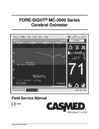
FORE-SIGHT® MC-2000 Series Cerebral Oximeter
Field Service Manual
21-02-0250 Rev 00 09/09
FORE-SIGHT Field Service Manual
Page intentionally left blank
Page 2
21-02-0250 Rev 00 09/09
FORE-SIGHT Field Service Manual
FORE-SIGHT MC-2000 Series Monitor MODEL DESCRIPTION MC-2000
Dual Channel Cerebral Oximeter, small battery (for use with Medium and Large sensors)
MC-2010
Dual Channel Cerebral Oximeter with battery backup (for use with Medium and Large sensors)
MC-2020
Dual Channel Universal Cerebral Oximeter, small battery (for use with all sensors)
MC-2030
Dual Channel Universal Cerebral Oximeter with battery backup (for use with all sensors)
IMPORTANT: This manual addresses all parameters of the FORE-SIGHT MC-2000 Series Monitor. You may have purchased a model that does not have all the parameters referred to in this manual. This Manual remains suitable for use. Read this Manual completely before using this equipment.
WARNING: The FORE-SIGHT MC-2000 Series Monitor is to be operated by qualified personnel only. Before use, carefully read this manual, including accessory directions for use, all precautionary information, and specifications. The user must check that the equipment functions safely and in proper working condition before use. First Printing: 09/2009
21-02-0250 Rev 00 09/09
Page 3
FORE-SIGHT Field Service Manual
HOW TO CONTACT US
CAS Medical Systems, Inc 44 East Industrial Road Branford, CT 06405 U.S.A.
Authorized Representative in European Union
Phone: (800) 227-4414 (203) 488-6056
MediMark® Europe. 11 rue E. Zola 38100 Grenoble. France
EC REP
Fax: (203) 488-9438 E-Mail: custsrv@casmed.com sales@casmed.com techsrv@casmed.com Web: www.casmed.com
Please contact the distributor in the country of purchase if product information or service should be required.
Copyright 2007 - 2009 CAS Medical Systems, Inc. All rights reserved. No part of this manual may be reproduced without the written permission of CAS Medical Systems, Inc. CAS reserves the right to make changes to this manual and improvements to the product it describes at any time without notice or obligation.
Page 4
21-02-0250 Rev 00 09/09
FORE-SIGHT Field Service Manual
Table of Contents 1
2
3
4
5
INTRODUCTION AND INTENDED USE
9
INTRODUCTION INDICATIONS FOR USE CONTRAINDICATIONS BRIEF DEVICE DESCRIPTION PATIENT ENVIRONMENT MANUAL OVERVIEW CONVENTIONS RELATED DOCUMENTS
9 9 9 9 10 10 10 10
SERVICE POLICY
11
WARRANTY POLICY EXTENDED CARE SERVICE PROGRAMS RETURNING THE MONITOR FOR REPAIR WEEE SELECTIVE TREATMENT AND RECYCLING INFORMATION
11 12 12 12
SAFETY MEASURES AND WARNINGS
13
AUTOMATIC SAFETY FEATURES MANUFACTURERS DECLARATION OF CONFORMITY
17 18
SYMBOLS
21
SYMBOLS ON MONITOR SYMBOLS NEAR ACCESSORY CONNECTIONS SYMBOLS APPEAR ON PACKAGING IN PLACE OF TEXT
21 21 21
MONITOR CONTROLS
23
FRONT PANEL FRONT PANEL CONTROLS / SYMBOLS On / Standby Key Alarm Silence / Reset Key Average / Auto / Left / Right Key Sensor Start / Restart Key Rotary Control Knob Symbols REAR PANEL
23 23 23 24 24 24 25 25 26
21-02-0250 Rev 00 09/09
Page 5
FORE-SIGHT Field Service Manual
6
7
8
9
Page 6
EXTERNAL DEVICE INTERFACING
27
OVERVIEW SELECTING THE SERIAL PORTS CONNECTING TO PHILIPS INTELLIVUE FORE-SIGHT SERIAL PORT DATA OUTPUT Simple Comma Text Test Port Printer USB
27 28 30 31 31 32 32 33
ROUTINE MAINTENANCE
35
CLEANING Cleaning Overview THE MONITOR THE DISPLAY CLEAN MONITOR CABLES CLEANING PATIENT CABLES FIBER OPTIC CONNECTORS SAFETY CHECKS SYSTEM CHECKS PREVENTATIVE MAINTENANCE BATTERY
35 35 35 35 36 36 36 36 37 37 37
TROUBLESHOOTING
39
HOW DOES THE FORE-SIGHT CEREBRAL OXIMETER WORK? LOCATION of LASER LABELS SYSTEM TROUBLESHOOTING SctO2 USER MESSAGES Error Messages in the Message Window
39 40 41 45 46
MAINTENANCE PROCEDURES
49
INTRODUCTION Equipment Required Data Sheet Battery Charge Turning the FORE-SIGHT MC-2000 Series Monitor “On” Displaying the Date and Time Alarm Audio
49 49 49 49 50 50 50
21-02-0250 Rev 00 09/09
FORE-SIGHT Field Service Manual OXIMETRY SIMULATION CHECK SctO2 Simulator Check ELECTRICAL SAFETY CHECKS Leakage DATA SHEET
10 SERVICE PROCEDURES INTRODUCTION Tools Required AC FUSE BATTERY FUSE Disconnecting the Battery Replacing the Battery Fuse CALLING CASMED for an RMA NUMBER CUSTOMER CARE PLAN
51 51 51 51 53
55 55 55 55 56 57 58 59 61
11 SPARE PARTS
63
12 SPECIFICATIONS
65
SctO2 MEASUREMENT LASER INFORMATION PATIENT ALARMS DISPLAY PHYSICAL DIMENSIONS AND WEIGHT OPERATING ENVIRONMENT STORAGE/TRANSPORT ENVIRONMENT POWER SERIAL INTERFACE STANDARDS
21-02-0250 Rev 00 09/09
65 65 65 66 66 66 66 66 67 67
Page 7
FORE-SIGHT Field Service Manual
Figures Figure 1: Patient Environment
10
Figure 2: Front Panel View
23
Figure 3: Clockwise and Counterclockwise Directions
25
Figure 4: Rear Panel View
26
Figure 5: RS232 Connector Pin Layout
27
Figure 6: Ports
29
Figure 7: Port Setup
29
Figure 8: Ports
32
Figure 9: USB Connector Pin Layout
33
Figure 10: Location of Internal Laser Labels
40
Figure 11: FORE-SIGHT MC-2000 Series Monitor Overall Block Diagram
41
Figure 12: No Monitor Power
42
Figure 13: Power up Response
43
Figure 14: SctO2 Trouble Shooting
44
Figure 15: AC Fuse Placement
56
Figure 16: Battery Fuse Placement
58
Tables Table 1: DB9 Male Pin Out
27
Table 2: DB9 Female Pin Out
27
Table 3: User Messages
47
Table 4: System Error Definition
48
Page 8
21-02-0250 Rev 00 09/09
FORE-SIGHT Field Service Manual
1
INTRODUCTION AND INTENDED USE INTRODUCTION The FORE-SIGHT MC-2000 Series Monitor is a pre-configured monitor that can include the following measurement functions: •
Absolute cerebral tissue oxygen saturation (SctO2)
The FORE-SIGHT MC-2000 Series Monitor detects oxygenation changes in biological tissue mainly at the microcirculation level (capillary, arteriole, and venule) based on different absorption characteristics of the chromophores oxyhemoglobin (HbO2) and deoxyhemoglobin (Hb) in the near-infrared spectrum. A biological spectroscopic window exists at the wavelength range 660–940 nm in which Hb and HbO2 can be differentiated and measured. Brain tissue oxygen saturation (SctO2) is determined from the ratio ((HbO2) ⁄ (HbO2 + Hb)) × 100%, which assumes a mixture of venous to arterial to venous blood of 70/30, respectively.
INDICATIONS FOR USE The FORE-SIGHT® Cerebral Oximeter, Model MC-2000 Series is indicated for the continuous noninvasive monitoring of regional hemoglobin oxygen saturation of blood in the brain (SctO2). It is intended for use in any individual at risk for reduced-flow or noflow ischemic states. When used with FORE-SIGHT large sensors, the FORE-SIGHT MC-2000 Cerebral Oximeter Monitor is indicated for use with adults and children over 40Kg. When used with the FORE-SIGHT medium sensors, the FORE-SIGHT MC-2000 Cerebral Oximeter is indicated for use with small adults and children between 4 kg and 80 kg. When used with FORE-SIGHT small sensors the FORE-SIGHT MC-2000 Series Cerebral Oximeter Monitor is indicated for infants and neonates ≤ 8Kg.
CONTRAINDICATIONS •
The FORE-SIGHT MC-2000 Series Monitor sensor is contraindicated for use on patients with limited skin access or allergic reaction to electrode adhesive.
•
Disposable SctO2 sensors are contraindicated for use for prolonged periods. The sensor site must be checked at least every eight hours; and if the circulatory condition or skin integrity has deteriorated, the sensor should be applied to a different site.
•
Do not adhere sensors to underdeveloped, immature, compromised, or healing skin.
•
No other contraindications are known at this time.
BRIEF DEVICE DESCRIPTION The FORE-SIGHT MC-2000 Series Monitor utilizes a 6.4” TFT, color, VGA LCD Display integrated into a front bezel with dedicated keys and a rotary-encode control knob. The FORE-SIGHT MC-2000 Series Monitor is constructed using a full metal rear enclosure. Batteries, Power Supply and 2 NIRS Signal Acquisition Module (NSAM) mounted within the enclosure behind the front bezel. Each NSAM shall incorporate a proprietary algorithm and a Patient Cable that is placed on the forehead. The front panel allows connection to a USB flash memory stick. The rear panel allows connection to other devices including, but not limited to: an external printer, a multi-parameter vital signs monitor and IBM compatible or MAC PC for diagnostics and program downloading. 21-02-0250 Rev 00 09/09
Page 9
FORE-SIGHT Field Service Manual
The FORE-SIGHT MC-2000 Series Monitor shall be capable of operating on AC or internal batteries. When on AC the batteries shall be charging.
PATIENT ENVIRONMENT The FORE-SIGHT MC-2000 Series Monitor has been tested with specific parts of the “system” used within the Patient Environment. Figure 1, defines the Patient Environment.
Figure 1: Patient Environment
MANUAL OVERVIEW This manual contains block diagram information about the CAS FORE-SIGHT MC-2000 Series Monitor. Only qualified service personnel should service this product. It is the user’s responsibility to ensure that the product is properly maintained and that the monitor is in safe and proper operating condition before being put into use. Before servicing the CAS FORE-SIGHT MC-2000 Series Monitor, read the User’s Manual carefully. CAS Medical Systems, Inc. believes the information herein is complete and accurate, but accepts no liability for errors, omissions, or misrepresentations.
CONVENTIONS In this manual, “WARNING”, “CAUTION”, and “NOTE” mean the following: WARNING: Directions that warn of conditions that put the patient or the caregiver at risk. CAUTION: Directions that help to avoid damaging the monitor or losing data. NOTE: Directions that make it easier to use the monitor, something not readily apparent.
RELATED DOCUMENTS To perform test and troubleshooting procedures, you must know how to operate the monitor. Refer to the CAS FORE-SIGHT MC-2000 Series Monitor User’s Manual.
Page 10
21-02-0250 Rev 00 09/09
FORE-SIGHT Field Service Manual
2
SERVICE POLICY WARRANTY POLICY All products are sold by CAS Medical Systems, Inc. (CASMED®), under the warranties set forth in the following paragraphs. Such warranties are extended only with respect to the purchase of this product directly from CAS Medical Systems, Inc., or CASMED’s Authorized Distributors as new merchandise and are extended to the first buyer thereof, other than for resale. The CASMED FORE-SIGHT® Cerebral Oximeter monitor is warranted for a period of twelve (12) months. All products, if applicable, are warranted to be free from functional defects in materials and workmanship and to conform to the description of the product contained in the User Guide, published specifications, and accompanying labels and/or inserts, provided that the same is properly operated under conditions of normal use in accordance with applicable safety and regulatory requirements, and that replacements and repairs are made in accordance with the instructions provided by CAS Medical Systems, Inc. The same warranty conditions are made for a period of twelve (12) months with respect to the battery. A ninety (90) days warranty is provided for non-disposable accessories such as reusable monitor cables and other accessories provided by CASMED as part of the original purchase. CASMED warrants disposable or single-patient-use products, including SctO2 sensors for out-of-box failure only. Where the accessory is not a CAS Medical Systems, Inc., manufactured product, the manufacturer’s own warranty applies. Warranty of accessories purchased separately from listed suppliers will be the responsibility of such listed suppliers. Damage to any part through misuse, neglect, or accident, or by affixing any accessories or attachments other than CASMED manufactured accessories or attachments, is not covered by this warranty. The foregoing warranties shall not apply if the product has been configured, modified, adjusted or repaired other than by CAS Medical Systems, Inc., or by persons expressly authorized by CAS Medical Systems, Inc., or not in accordance with written instructions provided by CAS Medical Systems, Inc., or if the product has been subjected to misuse, negligence, or accident. CASMED reserves the right to perform warranty service operations in its own factory, at an authorized repair facility, or at the customers’ site. The sole and exclusive obligation of CAS Medical Systems, Inc., and Buyer’s sole and exclusive remedy under the above warranties, is limited to repairing or replacing, free of charge, a product which is reported in writing or via telephone to CAS Medical Systems, Inc., has a Return Merchandise Authorization (RMA) number assigned and which is returned during normal business hours, transporting charges prepaid to: CAS Medical Systems, Inc. 44 East Industrial Road Branford, CT 06405 USA Telephone: +1 203 488 6056 Fax: +1 203 488 9438 E-mail: custsrv@casmed.com
21-02-0250 Rev 00 09/09
Page 11
FORE-SIGHT Field Service Manual CAS MEDICAL SYSTEMS, INC. SHALL NOT BE OTHERWISE LIABLE FOR ANY DAMAGES INCLUDING, BUT NOT LIMITED TO, INCIDENTAL DAMAGES, CONSEQUENTIAL DAMAGES OR SPECIAL DAMAGES. THERE ARE NO EXPRESS OR IMPLIED WARRANTIES WHICH EXTEND BEYOND THE WARRANTIES HEREINABOVE SET FORTH. CAS MEDICAL SYSTEMS, INC. MAKES NO WARRANTY OF MERCHANTABILITY OR FITNESS FOR A PARTICULAR PURPOSE WITH RESPECT TO THE PRODUCT OR PARTS THEREOF.
EXTENDED CARE SERVICE PROGRAMS CAS Medical Systems offers an Extended Care Service Contract program for the CAS FORE-SIGHT MC-2000 Series Monitor. Contact CAS Medical Systems’ Customer Service Department for more information.
RETURNING THE MONITOR FOR REPAIR Before returning a product for repair you must obtain authorization from CAS Medical Systems. An RMA (Return Merchandise Authorization) number will be issued to you by our Service Department. Be sure to note this number on the outside of your shipping box. Returns without an RMA number will not be accepted for delivery.
NOTE: Save the original shipping container and it’s inside packing material should the monitor need to be returned for service. Refer to Page 4, How To Contact Us for important telephone numbers, fax numbers and email addresses.
WEEE SELECTIVE TREATMENT AND RECYCLING INFORMATION To facilitate the sound treatment of WEEE, information will be made available for current CASMED products upon request. EU distributors and treatment facility personnel may contact techsrv@casmed.com to obtain relevant information.
Page 12
21-02-0250 Rev 00 09/09
FORE-SIGHT Field Service Manual
3
SAFETY MEASURES AND WARNINGS WARNING: The FORE-SIGHT MC-2000 Series Monitor is defibrillator-proof. It may remain attached to the patient during defibrillation, but the readings may be inaccurate during use and less than twenty (20) seconds thereafter. The FORE-SIGHT MC-2000 Series Monitor is intended only as an adjunct in patient assessment. It must be used in conjunction with clinical signs and symptoms. DO NOT rely exclusively on the audible alarm system for patient monitoring. Adjustment of alarm volume to a low level during patient monitoring may result in a hazard to the patient. Remember that the most reliable method of patient monitoring combines patient assessment and close personal surveillance with correct operation of monitoring equipment. DO NOT place the FORE-SIGHT MC-2000 Series Monitor face against a surface. This will cause the alarm to be muffled. DO NOT place the FORE-SIGHT MC-2000 Series Monitor back against a surface. This will block the fan and cause the unit to overheat, shutting it off. DO NOT place the FORE-SIGHT MC-2000 Series Monitor or accessories in any position that might cause it to fall. DO NOT lift or pull the FORE-SIGHT MC-2000 Series Monitor by any cable. DO NOT place the FORE-SIGHT MC-2000 Series Monitor where the controls can be changed by the patient. DO NOT use the FORE-SIGHT MC-2000 Series Monitor for any purpose other than specified in this manual. Doing so will invalidate the monitor’s warranty. DO NOT connect more than one patient to a monitor. Leakage Current Test – The interconnection of auxiliary equipment, including a patient monitor or other patient-connected equipment, with this device may increase the total leakage current. When interfacing with other equipment, qualified biomedical engineering personnel must perform a test for leakage current before using it with patients. Serious injury or death could result if the leakage current exceeds applicable standards. The FORE-SIGHT MC-2000 Series Monitor is to be operated by qualified personnel only. This manual, accessory direction for use, all precautionary information, and specifications should be read before use. DO NOT expose the FORE-SIGHT MC-2000 Series Monitor to excessive moisture such as direct exposure to rain. Excessive moisture can cause the FORE-SIGHT MC2000 Series Monitor to perform inaccurately or fail. Explosion Hazard – DO NOT use the monitor in the presence of a flammable anesthetic mixture with air or with oxygen or nitrous oxide.
21-02-0250 Rev 00 09/09
Page 13
FORE-SIGHT Field Service Manual
WARNING DO NOT place containers containing liquids on or near the FORE-SIGHT MC-2000 Series Monitor. Liquids spilled on the monitor may cause it to perform inaccurately or fail. Patient Safety – If the monitor, cables, power cord or sensor are damaged in any way, discontinue use immediately. The FORE-SIGHT MC-2000 Series Monitor is not “Category AP or APG Equipment.” Electromagnetic Compatibility (EMC) – The equipment needs special precautions if it is placed close to a strong transmitter such as X-ray equipment, MRI devices, TV, AM/FM radios, police/fire stations, an amateur (“ham”) radio operator, an airport, or a cellular phone. Their signals could interfere with the monitor, which may result in disruption of performance of this device or prevent the clear reception of signals by the monitor. This equipment has been tested and found to comply with the limits for medical devices to the EN 60601-1-2: 2002, Medical Device Directive 93/42/EEC. These limits are designed to provide reasonable protection against harmful interference in a typical medical installation. This equipment generates, uses, and can radiate radio frequency energy and, if not installed and used in accordance with the instructions, may cause harmful interference to other devices in the vicinity. However, there is no guarantee that interference will not occur in a particular installation. If this equipment does cause harmful interference to other devices, which can be determined by turning the equipment off and on, the user is encouraged to try to correct the interference by one or more of the following measures: • Reorient or relocate the receiving device. • Increase the separation between the devices. Consult the manufacturer for help. Severe anemia and edema may cause erroneous or no SctO2 readings. If the integrity of the protective earth conductor is in doubt, the unit may be operated from the internal batteries by disconnecting the AC line cord completely from the unit. To ensure patient safety and preserve device performance, DO NOT place the monitor in any position that might cause it to fall. DO NOT lift or pull the monitor by any sensor cable or line as they could disconnect from the monitor, causing the monitor to fall on the patient. To avoid electric shock or device malfunction, liquids must not be allowed to enter the device. If liquids have entered a device, take it out of service and have it checked by a service technician before it is used again. The FORE-SIGHT MC-2000 Series Monitor provides “DRIP-PROOF” level of protection from ingress to moisture. DO NOT place liquids on top of the monitor. DO NOT immerse the monitor or power cord in water or any liquid. DO NOT gas sterilize or autoclave the monitor.
Page 14
21-02-0250 Rev 00 09/09
FORE-SIGHT Field Service Manual
WARNING DO NOT touch any part of non-medical electrical equipment and the patient at the same time after removal of covers, connectors, etc. Where the integrity of the external protective conductor in the installation or its arrangement is in doubt, EQUIPMENT shall be operated from its INTERNAL ELECTRICAL POWER SOURCE. Isolation of product from mains can only be achieved by removal of external power cord. Route all cables away from patient’s throat to avoid possible strangulation. DO NOT, under any circumstances, perform any testing or maintenance on the monitor or power cord while the unit is being used to monitor a patient. Unplug the power cord before cleaning or servicing the monitor. The operator should not perform any servicing except as specifically stated in this manual. The functions of the alarm system for monitoring of the patient must be verified at regular intervals. Periodically, and whenever the integrity of the product is in doubt, test all functions. DO NOT use a frayed or damaged Power Supply cord or any accessory if you notice any sign of damage. Contact CAS Medical Systems, Inc., for assistance. DO NOT come into contact with patients during defibrillation. Otherwise serious injury or death could result. Only use CASMED-supplied patient cables with this monitor. The use of unprotected patient cables creates the potential for making an electrical connection to ground or to a high voltage power source which can cause serious injury or death to the patient. DO NOT modify or alter the SctO2 sensor in any way. Alterations or modification may affect performance and/or accuracy. The use of accessory equipment not complying with the equivalent safety requirements of this equipment may lead to a reduced level of safety of the resulting system. Consideration relating to the choice shall include: -
Use of the accessory in the patient environment.
-
Evidence that the safety certification of the accessory has been performed in accordance to the appropriate IEC 60601-1 and/or IEC 60601-1-1 harmonized national standard.
21-02-0250 Rev 00 09/09
Page 15
FORE-SIGHT Field Service Manual CAUTION For continued safe use of this equipment, it is necessary that the listed instructions be followed. However, instructions listed in this manual in no way supersede established medical practices concerning patient care. The Battery fuse must be installed for the unit to operate with the internal batteries. If the unit is not to be used for periods greater than 1 week, the battery fuse should be removed. The USB connector only accommodates a USB flash memory stick; DO NOT connect any other USB device or cable to the USB connector Qualified biomedical engineering personnel only must interface monitoring equipment with other types of medical equipment. Be certain to consult manufacturers’ specifications to maintain safe operation. Measurements may be affected in the presence of strong electromagnetic sources such as an electrosurgery unit (ESU). Pressing the front panel keys with a sharp or pointed instrument may permanently damage the switch membrane. Press the keys using only your finger. If the monitor is accidentally wetted, take it out of operation. It should be thoroughly dried. Inspect the monitor, cables, power cord and sensors for damage prior to operation. If any damage is noted, the monitor should not be used until it has been serviced. Only personnel authorized to do so by CAS Medical Systems, Inc., should repair the monitor. If the monitor fails to respond, DO NOT use it until the situation has been corrected by qualified CAS Medical Systems, Inc., personnel. Grounding reliability can only be achieved when the equipment is connected to an equivalent receptacle marked “Hospital Grade”. Use only accessories and sensors approved by CAS Medical Systems, Inc., to ensure patient safety and to preserve the integrity, accuracy, and electromagnetic compatibility of the monitor. Electrosurgery – To prevent unwanted skin burns; apply electrosurgery electrodes as far as possible from all other sensors, a distance of at least 15 cm (6 in.) is recommended. Federal law restricts this device to sale by or on the order of a physician or properly licensed practitioner.
Page 16
21-02-0250 Rev 00 09/09
FORE-SIGHT Field Service Manual GENERAL NOTES The FORE-SIGHT MC-2000 Series Monitor is designed for continuous operation. The FORE-SIGHT MC-2000 Series Monitor is suitable for use in the presence of electrosurgery; however, measurements may be inaccurate during active use of an ESU. The monitor is shipped with the appropriate line cord for the country and voltage being used. The FORE-SIGHT MC-2000 Series Monitor can remain connected to the patient during cardio defibrillation. All other applied parts are “Type BF Defibrillation Proof.” The monitor has been designed to promote patient safety. All equipment parts are protected against the effects of the discharge of a defibrillator. No separate actions are required when using this equipment with a defibrillator. There are no known risks with common disposal of equipment or accessories; however, the disposing of accessories should follow in accordance with local hospital policies. The user should ensure these policies do not conflict with any local, state, or federal guidelines.
AUTOMATIC SAFETY FEATURES All equipment parts are protected against the effects of the discharge of a defibrillator. No separate actions are required when using this equipment with a defibrillator. For FORE-SIGHT Model numbers 2010 and 2030, should the AC line power be interrupted coming into the monitor, the monitor automatically runs off battery power. An indication of this would be the Battery Indicator LED illuminates, three (3) audible beeps are heard and the message “Loss of AC Power” is displayed in the Message Area on the screen. CAUTION: Regardless of these safety features, always be sure to check that there are no signs of prolonged impairment of circulation and that the monitor is functioning properly.
21-02-0250 Rev 00 09/09
Page 17
FORE-SIGHT Field Service Manual
MANUFACTURERS DECLARATION OF CONFORMITY Manufacturers Declaration of Conformity Electronic Emissions and Immunity The FORE-SIGHT MC-2000 Series Monitor is intended for use in the electromagnetic environment specified below. The customer or the user of the FORE-SIGHT MC-2000 Series Monitor should assure it is used in such an environment. Emissions Test Compliance Electromagnetic Environment RF emissions – CISPR 11 Group 1 The FORE-SIGHT MC-2000 Series Monitor uses RF energy only for its internal function. Therefore, its RF emissions are very low and are not likely to cause any interference in nearby electronic equipment. RF emissions – CISPR 11 Class B The FORE-SIGHT MC-2000 Series Monitor is suitable for use in all Harmonic emissions establishments other than domestic establishments and those Class A IEC 61000-3-2 directly connected to the public low-voltage Power Supply network Voltage fluctuations / flicker Complies that supplies buildings used for domestic purposes. emissions Immunity Test
IEC 60601 Test Level
Compliance Level
Electrostatic discharge (ESD) IEC 61000-4-2
Level 3
Level 3
Electrical fast transient/burst IEC 61000-4-4
±2 kV for Power Supply lines ±1 kV for input/output lines
±2 kV for Power Supply lines ±1 kV for input/output lines
Surge IEC 61000-4-5
±1 kV line(s) to line(s) mode ±2 kV line(s) to earth mode < 5% UT (> 95% dip in UT) for 0.5 cycle. 40% UT (60% dip in UT) for 5 cycles. 70% UT (30% dip in UT) for 25 cycles. < 5% UT (> 95% dip in UT) for 5 s
±0.5 kV line(s) to line(s) mode ±2 kV line(s) to earth mode < 5% UT (> 95% dip in UT) for 0.5 cycle. 40% UT (60% dip in UT) for 5 cycles. 70% UT (30% dip in UT) for 25 cycles. < 5% UT (> 95% dip in UT) for 5 s
Voltage dips, short interruptions and voltage variations on Power Supply input lines IEC 61000-4-11
3 A/m 3 A/m Power frequency (50/60 Hz) magnetic field IEC 61000-4-8 NOTE: UT is the A.C. mains voltage prior to application of the test level.
Page 18
Electromagnetic Environment Guidance The FORE-SIGHT MC-2000 Series Monitor is designed for use in controlled environments only. Per OSHA guidelines for operating rooms, the area must employ adequate static electricity controls. The relative humidity should be maintained at about 50%. The FORE-SIGHT MC-2000 Series Monitor is designed for use in controlled environments only. Per OSHA guidelines for operating rooms, the Mains power quality should be that of a typical commercial or hospital environment. Mains power quality should be that of a typical commercial or hospital environment. Mains power quality should be that of a typical commercial or hospital environment. If user of the FORESIGHT MC-2000 Series Monitor requires continued operation during power mains interruptions, it is recommended that the FORE-SIGHT MC-2000 Series Monitor be powered from an uninterruptible Power Supply or a battery. Power frequency magnetic fields should be at levels characteristic of a typical location in a typical commercial or hospital environment.
21-02-0250 Rev 00 09/09
FORE-SIGHT Field Service Manual
Guidance and Manufacturer’s Declaration – Electromagnetic Immunity The FORE-SIGHT MC-2000 Series Monitor is intended for use in the electromagnetic environment specified below. The customer or the user of the FORE-SIGHT MC-2000 Series Monitor should insure that it is used in such an environment. Immunity Test IEC 60601 Test Level Compliance Electromagnetic Environment – Guidance Level Portable and mobile RF communications equipment should be used no closer to any part of the Model MC-2000 Series Monitor, including cables, than the recommended separation distance calculated from the equation applicable to the frequency of the transmitter. Conducted RF IEC 61000-4-6
3 Vrms 150 kHz to 80 MHz
3 Vrms
Radiated RF IEC 61000-4-3
3 V/m 80 MHz to 2.5 GHz
3 V/m
Recommended separation distance: d = 1.2√P d = 1.2√P 80 MHz to 800 MHz d = 2.3√P 800 MHz to 2.5 GHz Where P is the maximum output power rating of the transmitter in watts according to the transmitter manufacturer and d is the recommended separation distance in meters. Field strengths from fixed RF transmitters, as a determined by an electromagnetic site survey , should be less than the compliance level in each b frequency range. Interference may occur in the vicinity of equipment marked with the following symbol:
NOTE 1 At 80 MHz and 800MHz, the higher frequency range applies. NOTE 2 These guidelines may not apply in all situations. Electromagnetic propagation is effected by absorption and reflection from structures, objects and people. a Field strengths from fixed transmitters, such as base stations for radio (cellular / cordless) telephones and land mobile radios, amateur radio, AM and FM radio broadcast and TV broadcast cannot be predicted theoretically with accuracy. To assess the electromagnetic environment due to fixed RF transmitters, an electromagnetic site survey should be considered. If the measured field strength in the location in which the Model MC-2000 Series Monitor is used exceeds the applicable RF compliance level above, the 2040 Monitor should be observed to verify normal operation. If abnormal performance is observed, additional measures may be necessary, such as re-orienting or relocating the Model MC-2000 Series Monitor. b
Over the frequency range 150 kHz to 80 MHz, field strengths should be less than 3 V/m.
Recommended Separation Distances Between Portable and Mobile RF Communications Equipment and the Model 2040 Monitor The Model MC-2000 Series Monitor is intended for use in an electromagnetic environment in which radiated RF disturbances are controlled. The customer or the user of the Model MC-2000 Series Monitor can help prevent electromagnetic interference by maintaining a minimum distance between portable and mobile RF communications equipment (transmitters) and the Model MC2000 Series Monitor as recommended below, according to the maximum output power of the communications equipment. Separation distance according to frequency of transmitter (Meters) Rated maximum output power of transmitter (Watts)
150 kHz to 80 MHz
80 MHz to 800 MHz
d = 1.2√P
d = 1.2√P
800 MHz to 2.5 GHz d = 2.3√P
0.01 0.12 0.12 0.23 0.1 0.38 0.38 0.73 1 1.2 1.2 2.3 10 3.8 3.8 7.3 100 12 12 23 For transmitters operating at a maximum output power not listed above, the recommended separation distance d in meters can be estimated using the equation applicable to the frequency of the transmitter, where P is the maximum output power rating of the transmitter in watts according to the transmitter manufacturer. NOTE 1 At 80 MHz and 800 MHz, the separation distance for the higher frequency range applies. NOTE 2 These guidelines may not apply in all situations. Electromagnetic propagation is affected by absorption and reflection from structures, objects, and people.
21-02-0250 Rev 00 09/09
Page 19
FORE-SIGHT Field Service Manual
Page intentionally left blank
Page 20
21-02-0250 Rev 00 09/09