Quick Guide
2 Pages
Preview
Page 1
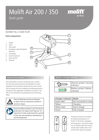
Molift Air 200 / 350 Quick guide
QG16601 Rev. A 2020-10-29 1
Hoist components:
2 1. 2. 3. 4. 5. 6. 7. 8.
Trolley Hoist Side covers Emergency stop/ Emergency lowering Lifting belt Quick release pin Hand control Sling bar
3 4 5 7 6
General information:
8
Battery / Charger indicator:
Lift and transfer of a client will always pose a certain risk and only trained personnel are allowed to use the equipment and accessories covered by this user manual. The rail system must be installed by certified personnel in accordance with applicable installation instructions. The lifter is not intended to be operated by the client being lifted. Only certified personnel are allowed to open hoist or accessories to perform service or repair. Read User Manual before use! This Quick guide does not replace User Manual. It is important to fully understand the content of the user manual before attempting to use the equipment.
Wrench symbol / Service indicator Battery symbol / Battery indicator
Charger indicator Green flash Yellow Yellow flash Green
Mode Not connected to hoist Charging Top of charge Fully charged
The Hand control has 2 buttons for lifting and lowering, or 4 buttons if the hoist is equipped with propulsion. The Hand control has an indicator light that will illuminate when battery level is low and the lifter requires charging
Lifter installation on trolley in rail
Emergency stop
Pull to activate emergency stop. The button will come out, and hoist will stop.
Connect one point first. Push button all the way in, and place lifter in connection point on trolley. Release button and make sure it is clearly showing green before connecting the next point.
Push with finger or use tube on cord to push button back in to reset emergency stop.
Electrical emergency lowering
Make sure both connection point buttons completely return and clearly show green after installation. Emergency lowering cord and tube can be adjusted to the correct length (height) by cutting tube and cord. Use this checklist to verify that the hoist is properly installed and can operate correctly and safely before use. End stops on rail are installed after mounting of trolley as described in BM4401 Make sure that the hoist is properly fastened to the rail and that the lift does not have any loose parts. Perform one lift with load (60-80 kg) Make sure battery is fully charged.
Pull and hold to start lowering. Hold until client is lowered and can be released from sling bar.
Only for emergency use when hand control does not work!
Lifting and lowering
Mounting suspension
1
2
3
4
1. 2. 3. 4.
Align sling bar in connection point. Push button on locking pin and insert all the way through. Make sure locking pin is properly fastened Push and hold down the button on the locking pin, and pull to remove locking pin.
The sling bars hook design prevents sling to be inadvertently detached when mounted correct.