FEHLING INSTRUMENTS
CERAMO TURNUS PUNCHES Assembly Instructions
2 Pages
Preview
Page 1
1
FEHLING
M 17
INSTRUMENTS
1-10/11
ASSEMBLY INSTRUCTIONS
CERAMO® TURNUS PUNCHES 1
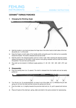
Changing the Working Angle
1
2
a)
Hold the handle in one hand and place the finger tips of the other hand on both sides of the handle profile (no. 1) of the shaft.
b)
Keep the fingers on both sides of the handle profile and gently push the shaft as far as possible toward the handle. The shaft is released and can be turned.
c)
Hold the shaft in the released position and turn it left or right. After reaching the desired position release the pressure on the shaft. A click sound in the spring indicates that the shaft has locked into position. You can now use the punch.
d)
The shaft can be locked in 8 different angle positions: 0°, 45°, 90°, 135°, 180°, 225°, 270° and 315°.
2
Disassembly
a)
Push the locking lever (no. 2) upward. The shaft is released from the handle and can be easily pulled out.
4
5
6
3
b)
Turn the pin (no. 3) counterclockwise, to screw it out of the slider (no. 4). Withdraw the pin with spring (no. 6) from the shaft and then remove the spring from the pin.
c)
Push the slider (no. 4) slightly towards the proximal shaft end (no. 5), pull it upward and remove it.
d)
Place all 4 parts of the shaft (pin, spring, slider and shaft) in the same container for reprocessing.
2
FEHLING
M 17
INSTRUMENTS
1-10/11
3
ASSEMBLY INSTRUCTIONS
Assembly
All threads, moving components and their backing bearings must be oiled sufficiently before the assembly. When assembling the shaft, observe that only the appropriate component parts (applies to shaft and slider only) are assembled. This can be verified by means of the lased identification number or the lot number stamped on the inside. Screws and springs fit on all shafts. a)
Place the spring (no. 6) over the pin (no. 3).
Slider
7
8
10
9
Shaft
b)
Place the slider with the guide (no. 7) on the T-section (no. 8) of the shaft and slide it a little to the distal side (jaw). Then the rear cut-in part of the slider (no. 9) can be placed in its guide (no. 10).
c)
Slide the slider (no. 4) app. 2 mm to the distal side, until it sits flush on the small step (a) in the shaft.
d)
Slide the pin (no. 3) with the spring (no. 6) installed through the hole at the proximal end (b) of the shaft and screw the external thread of the pin (c) in the internal thread of the slider up to the stop by turning it clockwise. The slider should be slightly pushed against the shaft.
a
b
c
Now the shaft can be inserted in the handle. ATTENTION: In order for the return mechanism of the TRADITION handle (TGZ-6A) to function properly, the handle element (no. 11) must be in closed position when the shaft is inserted. To make sure that the handle element is in the correct position, hold the handle such that the handle with the shaft socket (no. 12) shows upward when the shaft is inserted.
12 11
Grab the assembled shaft on both sides of the handle profile (no. 1) and push it into the handle until you hear a click sound. After a functional test the punch is ready to use.
FEHLING Hanauer Landstr. 7A · 63791 Karlstein/Germany · www.fehling-instruments.de INSTRUMENTS +49 (0) 61 88 – 95 74.40 · +49 (0) 61 88 – 95 74.45 · [email protected]