Service Manual
528 Pages
Preview
Page 1
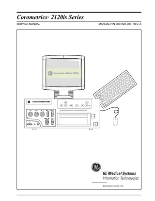
Corometrics 2120is Series ®
SERVICE MANUAL
MANUAL P/N 2007825-003 REV. A
Corometrics Model 2120is
Corometrics Model 2120is
Alarm Silence
NBP Go/Stop
US
US2
UA
FSpO2
MSpO2
FECG/MECG
NBP
UA Reference
Record
ChartLight
Twins Offset
Mark
Paper Advance
Power
!
1 0 !
Corometrics 2120is Series ®
SERVICE MANUAL
MANUAL P/N 2007825-003 REV. A
Corometrics Model 2120is
Corometrics Model 2120is
Alarm Silence
NBP Go/Stop
US
US2
UA
FSpO2
MSpO2
FECG/MECG
NBP
UA Reference
Record
ChartLight
Twins Offset
Mark
Paper Advance
Power
!
1 0 !
GUARANTEE All equipment sold by GE Medical Systems Information Technologies, is fully guaranteed as to materials and workmanship for a period of 1 year. GE reserves the right to perform guarantee service operations in its own factory, at an authorized repair station, or in the customer’s installation. Our obligation under this guarantee is limited to repairing, or, at our option, replacing any defective parts of our equipment, except fuses or batteries, without charge, if such defects occur in normal service. Claims for damage in shipment should be filed promptly with the transportation company. All correspondence covering the instrument should specify the model and serial numbers. GE MEDICAL SYSTEMS Information Technologies A GE Medical Systems Company
GE Medical Systems Information Technologies will make available on request such circuit diagrams, component diagrams, component parts lists, descriptions, calibration instructions, or other information which will assist the users or appropriately qualified technical personnel to repair those parts of the equipment which are classified by GE as repairable. Refer to the service manual for further information.
! CAUTION: In the United States of America, Federal Law restricts this device to sale by or on the order of a physician. Corometrics and Marquette are registered trademarks of GE Medical Systems Information Technologies. GE is a registered trademark of General Electric Company. All other product and brand names are trademarks or registered trademarks of their respective companies. ©2001-2004 GE Medical Systems Information Technologies. All rights reserved. No part of this manual may be reproduced without the permission of GE Medical Systems Information Technologies.
Contents
1
Safety... 1-1 General Information... 1-2 General Use... 1-2 Responsibility of the Manufacturer... 1-2 Responsibility of the User... 1-2 Definitions of Terminology... 1-3 Monitor Contraindications, Warnings, and Precautions... 1-4 Warnings... 1-4 Cautions... 1-7 Electromagnetic Interference... 1-8 Equipment Symbols... 1-9 Medical Device Reporting... 1-10 What is Medical Device Reporting (MDR)?... 1-10 What, When, and Where to Report... 1-10 Where to Get MDR Materials... 1-11 National Technical Information Service (NTIS)... 1-11 Internet... 1-11 FDA via Telephone... 1-11
2
Introduction... 2-1 Indications for Use... 2-2 Fetal Monitoring... 2-2 Maternal Monitoring... 2-2 Blood Pressure... 2-2 Pulse Oximetry... 2-2 Heart/Pulse Rate... 2-2 Bed-to-Bed Surveillance... 2-2 Series Overview... 2-3 The Model 2126is Monitor... 2-3 The Model 2128is Monitor... 2-5 The Model 2129is Monitor... 2-6 Upgrading Your Monitor... 2-6 Adding Fetal Movement Detection... 2-6
Revision A
2120is Series Maternal/Fetal Monitor 2007825-003
i
About the Manual... 2-7 Purpose... 2-7 Intended Audience... 2-7 Illustrations... 2-7 Pointing Devices... 2-8 Design Changes... 2-8 References to Persons, Places, and Institutions... 2-8
3
System Components... 3-1 Maternal/Fetal Monitor... 3-2 Networking Equipment... 3-5 UTP In-Wall Cable... 3-5 Patch Panels... 3-5 10Base-T Ethernet Hub... 3-6 RS-232 Serial Hub/Converter... 3-6 Junction Boxes... 3-7 Wallplates... 3-8 Dual Gang Wallplates... 3-8 Single Gang Wallplates... 3-9 Interconnection Cables... 3-10 Mobile Equipment Carts... 3-11 Isolation Transformers... 3-13 Optical Isolation Kit... 3-14 QS Office Client... 3-15 Uninterruptible Power Supply... 3-16 QS Office Client Power Backup... 3-16 Hub Backup Power... 3-17
4
Controls, Indicators, and Connectors... 4-1 Front Panel Description... 4-2 Local Window... 4-5 Model 2126is Numerics/Waveform Example... 4-9 Model 2128is Numerics/Waveform Example... 4-10 Model 2129is Numerics/Waveform Example... 4-11 Primary Labor Parameters... 4-12 Maternal Vital Signs... 4-15 Special Status Indicators... 4-18 Waveform Area... 4-19 Message Area... 4-19 Touch Screen Hotspots... 4-19
ii
2120is Series Maternal/Fetal Monitor 2007825-003
Revision A
Surveillance Window... 4-20 QS System Interface and Compact Window... 4-21 Rear Panel Description... 4-22
5
Theory of Operation... 5-1 Documentation Structure... 5-2 Main Motherboard (No. 2005881)... 5-4 Functional Overview... 5-4 Switch/Status Input Data Flow Diagram... 5-4 External/Internal Communication Data Flow... 5-4 Audio Control Flow... 5-4 Control Block... 5-25 Corolan Module... 5-26 Options Interface... 5-27 Rear Panel Interface... 5-27 Audio Section... 5-27 Recorder Interface Section... 5-28 RS-232C Communications Section... 5-28 DSP Board (No. 2001904-001)... 5-29 Functional Overview... 5-29 DSP Section... 5-29 Control Module... 5-29 Watchdog Module... 5-29 Status/Control Module... 5-30 Front-End Control/Status Interface... 5-30 IUP Interface... 5-30 Analog Conversion Module... 5-30 Front Panel Interface Section Theory... 5-31 Flasher Interface... 5-31 Front Panel Switch Interface... 5-31 Recorder LED Board Interface... 5-37 NBP Board (No. 14582, Sub-Assembly 13057)... 5-38 Pressure Transducer and Amplifier... 5-38 DC Pressure Amplifier and Filter... 5-38 AC Amplifier and Filter... 5-38 MUX and A/D... 5-39 Microcontroller and Host Interface... 5-39 Pump/Valve Control... 5-39 Communications Board (No. 2006067)... 5-40
Revision A
2120is Series Maternal/Fetal Monitor 2007825-003
iii
Telemetry Connector Board (No. 2006094)... 5-42 Telemetry System Interface... 5-42 Remote Event Marker Interface... 5-42 Fetal Acoustic Stimulator Interface... 5-42 System Power Supply... 5-44 Dual Ultrasound Board (No. 14806)... 5-45 Overview... 5-45 The Ultrasound Transducer... 5-45 Ultrasound Oscillator... 5-45 Digital Control Section... 5-46 Channel A Pin Diode Circuitry... 5-47 Channel B Pin Diode Circuitry... 5-47 Transmission, Channel A or Channel B... 5-48 Reception, Channel A or Channel B... 5-48 Channel A Filtering... 5-49 Main Filters... 5-49 Audio Circuitry... 5-49 Ultrasound Envelope... 5-50 Fetal Movement Filters... 5-50 UA/FECG Board (No. 11867)... 5-51 Isolated FECG Circuitry... 5-51 Isolated UA Circuitry... 5-52 MECG Board (No. 13691)... 5-60 Defibrillator Protection... 5-60 Input Lead Switching... 5-60 Single-Wire ECG Amplifier with Right Leg Drive... 5-61 Pacemaker Detection... 5-62 Leads Off Detection... 5-63 Test Generator... 5-65 Linear Isolation Amplifier... 5-65 Low-Pass and Notch Filters... 5-66 Oximeter Carrier Board (No. 13551)... 5-69 MSpO2 Board... 5-70 Functional Overview... 5-70 LED Driver Circuitry... 5-70 Input Source Selection Circuits... 5-71 Input Amplifier and Synchronous Detector... 5-71 Filters/Amplifiers... 5-72 Analog-to-Digital Conversion Circuitry... 5-73 Communications... 5-73 Processor Circuitry... 5-73
iv
2120is Series Maternal/Fetal Monitor 2007825-003
Revision A
Isolated Power Supply Board (No. 2003035)... 5-74 Controller...5-74 External Synchronization... 5-75 Fly-back Transformer, Output Rectification, and Filtering...5-75 Isolated Feedback...5-76 Short Circuit Protection... 5-77 Input Filter/Isolation Barrier...5-77 Recorder Board (No. 2003039)... 5-80 Host Board (No. 2005899)... 5-85 Processor... 5-86 I/O Companion Multi-Function South Bridge...5-86 PC97317 Super I/O Chip... 5-88 SODIMM...5-89 Serial Port Drivers / Parallel Port Connector...5-89 CODEC (Coder/De-Coder)...5-89 Dual Port RAM, Boot ROM, Disk On Chip, and Address Decoder...5-89 ISA Debugging Connector, Main Board Connector, and ISA Address Latch . . . 5-91 PCI Connector...5-91 MK1491 Clock Synthesizer... 5-92 Power Supply Section (Reset Circuit, VCC Core Generator, and VCC3V Source) .592 Flat Panel Video Interface...5-93 DP83815 10/100 Mb/s Integrated PCI Ethernet Media Access Controller and Physical Layer...5-93 Host Connector Board (No. 2005903)... 5-96
6
Setup Procedures... 6-1 Loading Strip Chart Recorder Paper... 6-2 Power... 6-6 Unit Labels... 6-9 Self-Test Routine... 6-10 Setup Windows... 6-11 Selecting Mode Title Hotspots...6-11 Selecting Setup Buttons... 6-12 Selecting Options...6-12 FECG Setup Window... 6-13 US/US2 Setup Window... 6-14 Maternal NBP Setup Window... 6-16 MHR/P Setup Window... 6-18 MSpO2 Setup Window... 6-20 Waveform Setup Window... 6-21
Revision A
2120is Series Maternal/Fetal Monitor 2007825-003
v
Master Alarm Setup Window... 6-22 Audio Alarms... 6-23 Re-Alarm... 6-23 Master Volume... 6-23 Alarm Limits... 6-23 General Setup Window... 6-24 Time... 6-25 Date... 6-25 SpO2 Scale... 6-26 Play Song... 6-26 Song Volume... 6-26 Recorder Light... 6-26 Paper Speed... 6-26 Paper Chime... 6-26 Chime Volume... 6-26 FSpO2 Trace... 6-27 FSpO2 Print Interval... 6-27 MSpO2 Print Interval... 6-27 Accessing the Service Setup Windows... 6-28 Install Options Window... 6-30 Network Surveillance Method... 6-33 NBP One-Minute Interval... 6-33 FM Remote Mark... 6-33 Smart BP... 6-34 Heartbeat Coincidence... 6-34 ECG Artifact Elimination... 6-34 Corolan Address Checking... 6-35 Power-On Default Settings... 6-35 Factory Defaults... 6-35 Current (Last-Used) Settings... 6-35 Hospital Defaults... 6-35 Volume Exceptions... 6-36 FHR Alarms... 6-36 HR Offset... 6-37 VS Print Interval... 6-38 Scaling... 6-38 Line Frequency... 6-38 Default TOCO Reference... 6-39 Recorder Font Size... 6-39 J102 Testing Window... 6-40 Verifying the J102 Output... 6-41 Analog Ground... 6-41 HR1 and HR2... 6-41 UA... 6-41 HR1 Mode... 6-41 HR2 Mode... 6-41
vi
2120is Series Maternal/Fetal Monitor 2007825-003
Revision A
UA Mode... 6-41 Markout*, Check Paper*, FMD1, and FMD2... 6-41 Calibrating the J102 Output... 6-42 Managed Use Setup Window... 6-43 Network Communications Setup Window... 6-44 Serial Communications Window... 6-45 Baud Rate... 6-45 Protocol... 6-45 Software Version Window... 6-47 Hardware Configuration Switches... 6-48 Mounting the Strain Gauge for IUP Monitoring... 6-49
7
Functional Checkout Procedure... 7-1 Before You Begin... 7-2 Equipment Required... 7-2 General... 7-2 Self-Test Routine... 7-4 Front Panel Button Test... 7-7 Touch Screen Button Test... 7-8 Connecting the Model 325 Simulator... 7-9 MECG Test... 7-10 FECG Test... 7-14 Legplate Inspection... 7-19 Ultrasound Test... 7-20 Fetal Movement Detection Test... 7-23 Ultrasound Transducer Test... 7-25 Uterine Activity Test... 7-26 Tocotransducer Test... 7-29 Strain Gauge Transducer Test... 7-30
Revision A
2120is Series Maternal/Fetal Monitor 2007825-003
vii
Pattern Memory Test... 7-31 Dual Heart Rate Test (Non-Pattern)... 7-33 FECG/US Modes... 7-33 Dual Ultrasound Modes... 7-36 MSpO2 Test... 7-37 NBP Test... 7-38 Alarm Test... 7-39 Verifying the UNITY Surveillance Network... 7-42 Verifying the QS Office Client Network... 7-44
8
Calibration... 8-1 General... 8-2 Power Supply Voltages Verification... 8-3 Main Board Power Supply Voltages... 8-3 Isolated Power Supply Board Voltages... 8-4 Isolated FECG/UA Board Voltages... 8-4 Recorder Photosensor Calibration... 8-5 Adjusting the Paper-Out Photosensor... 8-6 Adjusting the Paper-Loading Sensor... 8-6 Touch Screen Display Calibration... 8-7 Trimline Tocotransducer Calibration... 8-9 Equipment Required... 8-9 Procedure... 8-9 Nautilus Tocotransducer Calibration... 8-12 Equipment Required... 8-13 Calibration Procedure... 8-14 Disassembly... 8-14 Calibration for Cat. No. (REF) 2264 GAX/HAX/JAX/KAX/LAX/MAX... 8-14 Calibration for Cat. No. (REF) 2264 AAX/BAX/CAX/DAX/EAX/FAX... 8-15 Reassembly... 8-16 Testing the Tocotransducer... 8-16 Maternal SpO2 Calibration... 8-17
viii
2120is Series Maternal/Fetal Monitor 2007825-003
Revision A
9
Self-Tests... 9-1 Power-On Diagnostic Tests... 9-2 Monitor Self-Test... 9-3 Event Log Window... 9-6 Windows CE Event Log... 9-6 2120is Monitor Event Log... 9-7 Diagnostic Control Window... 9-12 Maternal Blood Pressure Tests... 9-14 Monthly Manometer Pressure Check... 9-14 Quarterly Pneumatic Pressure Check... 9-16 Recorder Calibration Test... 9-17 Corolan Address Check... 9-17
10
Maintenance... 10-1 Cleaning... 10-2 Cleaning the Monitor Exterior... 10-2 Cleaning the Display, Mouse, and Keyboard... 10-2 Cleaning the Tocotransducer, Ultrasound Transducer, MECG Cables, and Legplate 10-3 Cleaning the UA Strain Gauge... 10-4 Cleaning the Maternal NBP Cuffs and Hoses... 10-4 Batteries... 10-5 Host Board Battery... 10-5 Main Board Battery... 10-6 Preventative Maintenance Inspection... 10-8 Equipment Required... 10-8 Visual Inspection... 10-8 Cleaning... 10-9 Calibration... 10-9 Electrical Safety Tests... 10-9 Initial Conditions... 10-9 AC Line... 10-10 Ground Impedance... 10-10 Unit to Primary Leakage... 10-10 Patient-to-Ground Leakage for ECG... 10-11 Patient-to-Line Leakage for ECG... 10-12 Patient-to-Ground Leakage for IUP... 10-13 Patient-to-Line Leakage for IUP... 10-14 Patient-to-Ground Leakage for SpO2... 10-15 Patient-to-Line Leakage for SpO2... 10-16
Revision A
2120is Series Maternal/Fetal Monitor 2007825-003
ix
Ground Continuity... 10-16 Patient-to-Ground Leakage for US... 10-17 Patient-to-Line Leakage for US... 10-18 Patient-to-Ground Leakage for US2... 10-19 Patient-to-Line Leakage for US2... 10-20 Dielectric (Hi-Pot) Tests... 10-21 Patient–to–AC-Line Using DC Voltage for One Minute... 10-21 Patient–to–Chassis Using AC Voltage for One Minute... 10-23 Mains–to–Chassis Using DC Voltage for One Minute... 10-25 Ethernet-to-Chassis Using DC Voltage for One Minute... 10-25 Software Download Procedure... 10-26 Qualified Personnel... 10-26 Equipment Required... 10-26 Configuring the Transfer PC... 10-27 Recording Existing Monitor Settings... 10-29 Downloading the Monitor Software... 10-31 Troubleshooting... 10-38 Communication Error... 10-38 Windows Lock Up... 10-39 Disk Error... 10-39 Write Protect Error... 10-40 Known Incompatibilities... 10-40 Touch Screen Display Calibration... 10-41 Deleting the QS Office Client Connection... 10-42
11
Strip Chart Recorder Servicing... 11-1 Removing the Strip Chart Recorder... 11-2 Installing the Strip Chart Recorder... 11-3 Periodic Thermal Printhead Cleaning... 11-4 Field Serviceable Assemblies... 11-5 Stepper Motor and Harness... 11-5 Removing the Stepper Motor... 11-5 Replacing the Stepper Motor... 11-5 Printhead Adjustments... 11-6 Vertical Offset Adjustment... 11-6 Horizontal Offset Adjustment... 11-6 Thermal Printhead... 11-8 Paper-Low/Paper-Out Photosensors... 11-12 Removing the Paper-Low/Paper-Out Photosensor... 11-12 Replacing the Paper-Low/Paper-Out Photosensor... 11-12 Adjusting the Paper-Low Photosensor... 11-12 Adjusting the Paper-Out Photosensor... 11-13
x
2120is Series Maternal/Fetal Monitor 2007825-003
Revision A
Paper-Loading Sensor... 11-14 Removing the Paper-Loading Photosensor... 11-14 Replacing the Paper-Loading Sensor... 11-14 Adjusting the Paper-Loading Sensor... 11-15
12
Transducer Servicing... 12-1 Plug Replacement Kits... 12-2 Handling Precautions... 12-3 Equipment Required... 12-3 Tocotransducer Cable Preparation... 12-4 Ultrasound Transducer Cable Preparation... 12-6 MECG Cable Preparation... 12-9 FECG Cable Preparation... 12-12 Plug Assembly... 12-14
13
Peripheral Devices... 13-1 Front Panel Connectors... 13-2 Remote Marks Connector... 13-2 Remote Marks Connector... 13-2 J101 Connector (Model 340 Telemetry System Interface)... 13-3 Rear Panel Connectors... 13-4 ECG Out Connector... 13-4 J102 Connector (Spectra 400 Analog Interface)... 13-4 J108 Connector (Corolan Interface)... 13-4 J109, J110, and J111 Connectors (RS-232C)... 13-5 Baud Rate... 13-5 Mode... 13-5 Nellcor Puritan Bennett Model N-200 Maternal Pulse Oximeter... 13-7 DINAMAP Models 1846, 1846SX, and 1846SX/Oxytrack, 8100, and 8100T... 13-8 Quantitative Sentinel/Perinatal System... 13-9 Model 115-Compatible Communications Protocols... 13-10 115 Update Mode... 13-11 115 Transmit/Receive Mode... 13-12
Revision A
2120is Series Maternal/Fetal Monitor 2007825-003
xi
Requested Data Format... 13-12 Monitor Type... 13-12 Data Field... 13-12 End of Text... 13-12 Transmitted Data Format... 13-13 Monitor Type... 13-13 Response Type... 13-13 Monitor ID... 13-13 Data Field... 13-13 End of Text... 13-14 Limitations... 13-14 Error Conditions... 13-15 Transmission Errors... 13-15 Request Errors... 13-15 Cabling Information... 13-17 Monitor RS-232 Connector... 13-17 Standard RS-232C Rules... 13-17 Cable Distance... 13-17 Data Terminal Equipment Cabling... 13-17 Data Communications Equipment Cabling... 13-17
14
Troubleshooting... 14-1 General Troubleshooting... 14-2 Ultrasound Troubleshooting... 14-3 FECG Troubleshooting... 14-4 External Uterine Activity Troubleshooting... 14-5 Internal UA Troubleshooting... 14-6 MECG Troubleshooting... 14-7 Blood Pressure Troubleshooting... 14-8 Maternal Pulse Oximetry Troubleshooting... 14-9 Surveillance Troubleshooting (via 2120is Monitors)... 14-10 QS Interface Troubleshooting... 14-12
xii
2120is Series Maternal/Fetal Monitor 2007825-003
Revision A
15 16
Technical... 15-1 Specifications... 15-1 General Monitor... 15-2 Operating Modes
15-3
Strip Chart Recorder... 15-7
17 18
Drawings... 16-1 Parts Lists... 17-1 11821A, Recorder Printhead Assembly Parts List... 17-3 11867E, UA/FECG Board Parts List... 17-5 13057G, NBP Board Parts List... 17-9 13452A, Main Board Parts List... 17-13 13551A, Oximeter Carrier Board Parts List... 17-15 13690A, MSpO2 Front Panel Connector Board Parts List... 17-17 13691A, MECG Board Parts List... 17-19 14091A, Paper Orientation Sensor Board Parts List... 17-23 14582GREF, NBP Board Final Assembly Parts List... 17-25 5700GAX, Button-Style Nautilus Ultrasound Transducer Assembly Parts List (5-ft cord)... 17-27 5700KAX, Loop-Style Nautilus Ultrasound Transducer Assembly Parts List (5-ft cord)... 17-29 14806B, Dual Ultrasound Board Parts List... 17-31 2264AAX, Button-Style Nautilus Tocotranducer Assembly Parts List (5-ft cord) 1735
Revision A
2120is Series Maternal/Fetal Monitor 2007825-003
xiii
2264DAX, Loop-Style Nautilus Tocotransducer Assembly Parts List (5-ft cord) 1737 1509AAO/BAO, Qwik Connect Plus Legplate Assembly Parts List... 17-39 2001903, DSP/Front Panel Interface Parts List... 17-41 2003035, Isolated Power Supply Parts List... 17-45 2003039, Recorder Board Parts List... 17-47 2005880, Main Board (with Corolan Communications), Parts List... 17-49 2005899, Host Board Parts List... 17-53 2005903, Host Connector Board Parts List... 17-59 2006067, J102 Communications Board Parts List... 17-61 2006094, Telemetry Connector Board Parts List... 17-65 2006592, Front Bezel Assembly Parts List... 17-67 2007301-008, Generic Assembly Parts List... 17-69 2008400, Recorder Assembly Parts List... 17-73 2008401 Door Assembly Parts List... 17-75
19
xiv
Block Diagrams... 18-1
2120is Series Maternal/Fetal Monitor 2007825-003
Revision A
Figures Figure 3-1. 2120is Electronics Unit...3-2 Figure 3-2. Compact Keyboard...3-3 Figure 3-3. Keyboard with Trackball...3-3 Figure 3-4. Two-Button Mouse...3-3 Figure 3-5. Touch Screen Display...3-4 Figure 3-6. Unshielded Twisted Pair (UTP) In-Wall Cable...3-5 Figure 3-7. 110Connect Patch Panel...3-5 Figure 3-8. 10Base-T Patch Panels (12- and 24-Port Models)...3-6 Figure 3-9. RS-232 Serial Hub/converter...3-6 Figure 3-10. Dual Gang Wallplates...3-8 Figure 3-11. Single Gang Wallplates...3-9 Figure 3-12. Mobile Equipment Cart...3-12 Figure 3-13. Isolation Transformer...3-13 Figure 3-14. Opto-Isolator...3-14 Figure 3-15. QS Terminal Server...3-15 Figure 3-16. UPS for QS Office Client...3-16 Figure 3-17. UPS for Hub...3-17
Revision A
2120is Series Maternal/Fetal Monitor 2007825-003
xv
Figure 4-1. Model 2129is Front Panel...4-2 Figure 4-2. Local Window...4-5 Figure 4-3. Model 2126is Example, partial display...4-9 Figure 4-4. Model 2128is Example, partial display...4-10 Figure 4-5. Model 2129is Example, partial display...4-11 Figure 4-6. FHR Display...4-12 Figure 4-7. UA Display...4-14 Figure 4-8. NBP Display...4-15 Figure 4-9. MHR/P Display...4-16 Figure 4-10. MSpO2 Display...4-17 Figure 4-11. Special Status Indicators above the Waveform Area...4-18 Figure 4-12. Surveillance Window...4-20 Figure 4-13. Compact Window...4-21 Figure 4-14. 2120is Series Rear Panel Connectors...4-22 Figure 5-1. Main Motherboard Input Parameter Data Flow...5-5 Figure 5-2. Main Motherboard Switch Input Data Flow...5-5 Figure 5-3. Main Motherboard Communications Data Flow...5-6 Figure 5-4. Main Motherboard Audio Control Flow...5-6
Revision A
2120is Series Maternal/Fetal Monitor 2007825-003
xvi
Figure 5-5. Host Board Connector J6...5-20 Figure 5-6. Corolan Address Checking...5-26 Figure 6-1. Opening the Recorder Door...6-3 Figure 6-2. Fanning the Paper...6-3 Figure 6-3. Orienting the Paper...6-4 Figure 6-4. Creating a Paper Leader...6-4 Figure 6-5. Inserting the Paper...6-5 Figure 6-6. Closing the Recorder Door...6-5 Figure 6-7. Turning the Monitor On/Off...6-6 Figure 6-8. Attaching the Power Cord...6-6 Figure 6-9. Password Access Window...6-8 Figure 6-10. Selecting a Mode Title Hotspot...6-11 Figure 6-11. FECG Setup Window...6-13 Figure 6-12. US/US2 Setup Window...6-14 Figure 6-13. Maternal NBP Setup Window...6-16 Figure 6-14. MHR/P Setup Window: MSpO2 as the MHR/P Source...6-18 Figure 6-15. MSpO2 Setup Window...6-20 Figure 6-16. Waveform Setup Window...6-21
Revision A
2120is Series Maternal/Fetal Monitor 2007825-003
xvii