Installation Guide
20 Pages
Preview
Page 1
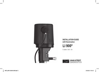
INSTALLATION GUIDE LED Illumination
LI 900® 5. Edition / 2013 – 04
© HAAG-STREIT AG, 3098 Koeniz, Switzerland - HS-Doc. no. 1502.7220285.02050 – 5. Edition / 2013 – 04
INST_LI900-7220285-02060.indd 1
DOK. no. 1500 1500.1400209.04000
1
23.04.2013 07:21:15
INSTALLATION GUIDE LED Illumination
LI 900® 6. Edition / 2013 – 04
General
The illumination head LI 900 may be combined with Slit Lamp types BQ 900, BM 900 and BP 900. The LI 900 is equipped with one or two individually adjustable LED’s. The first LED is used for slit illumination and the second for the background illumination. For powering the Slit Lamp, the traditional two pole connector cable is used. The operating voltage is 24V DC. In order that slit and background illumination may be operated individually, a communication signal is modulated on the two pin supply voltage cable. The communication between power supply PS-LED and LI 900 is based on power line technology.
Purpose of use
The LED illumination LI 900 has been designed exclusively for use of the slit lamps BQ 900, BM 900 and BP 900. • Slit and background illumination are continuously variable controlled by an illumination control box. • It is used to aid in the diagnosis of diseases or trauma which affects the structural properties of the anterior eye segment. FORBIDDEN! Newer use this set for other purposes.
2
INST_LI900-7220285-02060.indd 2
© HAAG-STREIT AG, 3098 Koeniz, Switzerland - HS-Doc. no. 1502.7220285.02050 – 5. Edition / 2013 – 04
23.04.2013 07:21:15
Contents 1.
Safety ...4
2.
Device description...5
1.1 1.2 1.4 1.8
2.1 2.1.1 2.1.2 2.1.3 2.2 2.2.1 2.2.2 2.3 2.3.1 2.3.2 2.3.1
Transport and unpacking... 4 Installation warning notices ... 4 Operation, environment... 4 Symbols... 4
PS-LED power supply unit... 5 Variant types... 5 Description... 5 LED indicator (Power supply)... 5 LED illumination LI 01x... 6 Variant types... 6 Description... 6 Factory settings... 6 Power supplies (PS-LED / PS-LED HSM 901) jumper settings... 6 Power supplies (PS-LED / PS-LED HSM 901) dipswitch settings ... 6 Controller options graph... 7
3.
Installation on tables...7
4
Upgrading ...9
3.1 3.2 3.3 3.4 3.4.1
4.1 4.2 4.4 4.4.1 4.4.2 4.5
Installation on HSM 901... 7 Installation on HSM 801 and third party tables... 7 Examples of an installation on pendulum Tables... 8 Use of existing potentiometers... 9 Error signalization... 9
5.
Error messages...12
6.
Incorrect polarization...13
6.
Drawings / Measurements...14
7.
Accessories...16
5.1 4.6
6.1 6.2 6.2.1 6.3
7.1 7.2 7.3 7.4 7.5 7.6 7.7 7.8
Illumination head... 12 Power supply unit PS-LED... 12
Illumination controller IC01... 14 Illumination controller IC01-T... 14 Illumination controller IC01-T recess (table top)... 14 Power supply PS-LED... 15
Illumination head... 16 Power supplies*... 16 Background illuminations... 16 Illumination control box 'in table'... 17 Illumination control box 'on table'... 17 Cables... 17 Dielectric mirror... 17 Instrument tables... 18
Mirror... 9 Removal of the old Illumination part and assembling the LED illumination Head... 9 Adjusting the LED Illumination head... 10 Newer LED version... 10 Older LED version... 10 Background illuminations... 11
© HAAG-STREIT AG, 3098 Koeniz, Switzerland - HS-Doc. no. 1502.7220285.02050 – 5. Edition / 2013 – 04
INST_LI900-7220285-02060.indd 3
3
23.04.2013 07:21:15
1. Safety
1.4 Operation, environment
FORBIDDEN! Not observing these notes will lead to material damage and the endangering of patients.
FORBIDDEN! Never operate the instrument in the same room with combustible gases, volatile solvents (alcohol, benzol) or flammable anaesthetic agents.
WARNING! These signs must be adhered strictly to ensure safe operation of the instrument and to avoid endangering users and patients.
WARNING! To avoid the risk of electric shock, the equipment should preferably be connected to a supply network with ground connection.
NOTE! Important notes! Please read carefully.
NOTE! • Only qualified and trained personnel should operate the equipment, the training is at the owner’s responsibility. Use only HAAG‑STREIT accessories. • Warranty claims will only be considered if the directions in the instructions for use have been followed as specified. • The manufacturer of this device is not liable for loss or damage due to its unauthorized handling. All consequent guarantee claims become invalid.
1.1 Transport and unpacking • Before you unpack the instrument, check whether the packing shows traces of
• • •
improper handling or damage. If this is the case, inform the haulier which has delivered the product to you. Unpack the instrument together with a representative of the haulier. Prepare a protocol describing parts that are possibly damaged. This must be signed by you and by the representative of the haulier. Leave instrument in the packing for several hours before unpacking (condensation). After unpacking, check if the instrument has been damaged. Return the defective equipment in an appropriate packaging.
1.8 Symbols
1.2 Installation warning notices
PS-LED has been designed to conform to the medical norm EN 60601-1. This safety standard may be lowered if the LED Illumination LI 900 is combined with other electrical systems. Alterations in installation have to be done in accordance with the Norm 60601-1-1 'Safety requirements for medical electrical systems'. For additional information refer to the instruction for use 'LED Illumination LI 900'. WARNING! Always mount the slit lamp and the headrest on an electric insulated and fire resistant table top. Only a hospital grade 3-conductor electrical power supply cable must be used. For USA and Canada: Detachable power supply cord set, UL listed, type SJE, SJT or SJO, 3-conductor, not smaller than 18 AWG. Plug, cable and ground lead connection of the socket have to be in perfect condition. 4
INST_LI900-7220285-02060.indd 4
12
Read the instructions for use carefully
General warnings: Read the accompanying documents
European Certificate of Conformity
Disposal note See chapter 'Environment'
Complies with the European Directive 2002/95/EC (RoHS)
Take off the mains plug before opening the device
China RoHS
Manufacturer
Year of Production
Continuous current
Alternating current
Power on
© HAAG-STREIT AG, 3098 Koeniz, Switzerland - HS-Doc. no. 1502.7220285.02050 – 5. Edition / 2013 – 04
23.04.2013 07:21:17
Power off
Functional earth
Protected against the ingress of water and foreign bodies
Serial number
HS reference number
Slit illumination
Background illumination
3
4 8
• The PS-LED power supply can only be used in combination with an illumination control box IC 01 and a LI 01 or LI 01 plus type LED light.
• The slit lamps BQ 900, BM 900 and BP 900 are powered by the power supplies PS-LED or PS-LED HSM 901.
2.1 PS-LED power supply unit
2.1.1 Variant types 1. Power supply unit PS-LED, for mounting on non-HS tables and units 2. Power supply unit PS-LED HSM 901 Slide-in type for HSM 901 instrument table
7
6
11
10
I O
9
3. Mains switch Switch in position 0 = ‘OFF’ Power supply is disconnected from mains Switch in position 1 = ’ON’ Control lamp shines green 4. 3-pole mains connection 5. Connection for slit and background illumination 6. Type plate (on housing) 7. Connection for HAAG‑STREIT illumination controller IC 01 (USB mini B) 8. Connection for non-HS illumination (slit illumination only) controller (power jack 2.1 mm) 9. Protective earth connection (M3) 10. L1, LED indicator green ‒ red (normal operation: green) 11. S1, Push button
2
© HAAG-STREIT AG, 3098 Koeniz, Switzerland - HS-Doc. no. 1502.7220285.02050 – 5. Edition / 2013 – 04
INST_LI900-7220285-02060.indd 5
5
Third-party Illumination control
2. Device description
1
2.1.2 Description
5
23.04.2013 07:21:19
2.2 LED illumination LI 01x
2.3.2 Power supplies (PS-LED / PS-LED HSM 901) dipswitch settings
2.2.1 Variant types 12. LED illumination LI 01-plus with background illumination 13. LED illumination LI 01 without background illumination
WARNING! Take off the mains plug before opening the device!
14
NOTE! Gently remove the protection cover using a large screwdriver as shown in the figure below.
15
12
16
13
17
2.3 Factory settings
2.3.1 Power supplies (PS-LED / PS-LED HSM 901) jumper settings WARNING! Take off the mains plug before opening the device! NOTE! Gently remove the protection cover using a large screwdriver as shown in the figure. The factory settings allow the use of an headrest with LED fixation lamp. In case you have an old type headrest (with a bulb as a fixation lamp instead of an LED), you have to plug the jumper (JP) to the “BULB” position. 6
INST_LI900-7220285-02060.indd 6
The factory settings for the slit and background illumination are set to progressive control. You may change the illumination option to linear control by setting the dipswitch no.4 to open. (The position 1, 2 and 3 will be defined for future settings.) Progressive light increment
Linear light increment
1 = Open 2 = Open 3 = Open 4 = Close
1 = Open 2 = Open 3 = Open 4 = Open 1
LED BULB
2.2.2 Description 14. VDC connector cable 15. Filter wheel for blue filter 16. Background illumination connection 17. Cover
JP
2
3
4
OPEN
© HAAG-STREIT AG, 3098 Koeniz, Switzerland - HS-Doc. no. 1502.7220285.02050 – 5. Edition / 2013 – 04
23.04.2013 07:21:24
Intensity
2.3.1 Controller options graph
18. LED illumination VCD connector 20. Illumination control box IC 01 / 01-1 22. Controller cover plate 24. Illumination control box IC 01T / 01T-1 26. Instrument table HSM 901 28. Instrument table HSM 801 or 3th party table
r
Linea
essive
Progr Control level
3.1 Installation on HSM 901
3. Installation on tables
NOTE! Find the mechanical dimensions of the illumination controllers, Power supplies and table recess in chapter 'Drawings'. 18
18
Installation on HSM 901
Installation on HSM 801 and 3th. party tables 19
20
19
20
21
21
22 23
23
24
24 25
25 28 29
115-230VAC 50-60Hz
115-230VAC 50-60Hz
27
© HAAG-STREIT AG, 3098 Koeniz, Switzerland - HS-Doc. no. 1502.7220285.02050 – 5. Edition / 2013 – 04
INST_LI900-7220285-02060.indd 7
a) Connect the power supply PS-LED HSM 901 (25) with the main lamp cable of the headrest. b) Connect the PS-LED HSM 901 (27) and the illumination controller (20/24) [IC 01, IC 01-1, IC 01T, IC 01T-1] with the illumination control cable (23). c) The illumination controller (20/24) [IC 01, IC 01-1, IC 01T, IC 01T-1] can be placed either to the right side or the left side of the table top. d) Cover the other side with the controller cover plate (22) [only if you use a table top LED].
3.2 Installation on HSM 801 and third party tables WARNING! Always mount the slit lamp and the headrest on an electric insulated and fire resistant table top.
22
26
19. Focusing Target 21. Headrest 23. Illumination control cable 25. Connection for slit and background illumination 27. Power supply PS-LED HSM 901 29. Power supply PS-LED HSM 901
a) Install the PS-LED (29) on the left or right side of the table plate bottom according to the illustration. (a drilling plan can be found in the chapter 'Drawings'). b) Connect the power supply PS-LED (25) with the main lamp cable of the headrest. NOTE! To use an existing or third party illumination controller see chapter 3.4 'Use of existing potentiometers'. c) The illumination controller (20/24) [IC 01, IC 01-1, IC 01T, IC 01T-1] can be placed either to the right side or the left side of the table top. (For recess mount controllers, a recess plan can be found in the chapter 'Drawings'). d) Connect the PS-LED (29) and the illumination controller (20/24) [IC 01, IC 01-1, IC 01T, IC 01T-1] with the illumination control cable (23). 7
23.04.2013 07:21:27
3.3 Examples of an installation on pendulum Tables WARNING! Only qualified and trained personnel should modify the equipment. The modifications are under the responsibility of the technician and must comply with the medical norm EN 60601-1.
24
23
115-230VAC 50-60Hz 115-230VAC 50-60Hz
PS-LED
NOTE! The unit electronically switches the mains input of the power supply using an isolated contact with respect to the table position. a) Check if the focusing target is powered by a bulb or by LED, see chapter 'Power supplies (PS-LED / PS-LED HSM 901) jumper settings' b) Disconnect the cable from the existing power supply and connect it to the power supply PS-LED.
INST_LI900-7220285-02060.indd 8
23
20
25
20
25
8
24
PS-LED
NOTE! For this installation, the cable between power supply and LED illumination has to be interrupted. Therefore an isolating contact, sensing the table position is needed. With this installation, the power supply is not disconnected from mains. NOTE! To use an existing or third party illumination controller see chapter 3.4 'Use of existing potentiometers'. c) The illumination controller (20/24) [IC 01, IC 01-1, IC 01T, IC 01T-1] can be placed either to the right side or the left side of the table top. (For recess mount controllers, a recess plan can be found in the chapter 'Drawings'). Suitable connecting cables are available from HAAG‑STREIT, see chapter 'Accessories'. d) Connect the PS-LED and the illumination controller (20/24) [IC 01, IC 01-1, IC 01T, IC 01T-1] with the illumination control cable (23).
© HAAG-STREIT AG, 3098 Koeniz, Switzerland - HS-Doc. no. 1502.7220285.02050 – 5. Edition / 2013 – 04
23.04.2013 07:21:30
3.4 Use of existing potentiometers NOTE! Only the slit illumination supports the use of existing or third party potentiometers. For background illumination only HAAG‑STREIT illumination controller can be used. Existing potentiometers may be used to control the slit illumination. The resistance value has to be between 5kΩ and 50kΩ.
4
Upgrading
4.1 Mirror
WARNING! Before you upgrade the system, make sure the HAAG‑STREIT dielectric mirror is used. If you have a mirror without the correct labeling, it has to be replaced, see chapter 'Accessories'.
Part. Nr. 1001590
Powerjack GND
Powerjack +
WARNING! Wire-wound potentiometers are not adequate. They may produce illumination flickers. The customer potentiometer has to be wired to PS-LED. Therefore a power-jack, available on request at HAAG‑STREIT AG is needed, see chapter 'Accessories'. Using a customer potentiometer requires the system to be calibrated: a) Turn potentiometer to its maximum position b) Switch power supply PS-LED in ON position c) Press button S1 on backside of power supply for about 1 second. The orange LED (L1) indicates that the calibrating process is in progress. d) After approximative 1 to 3 seconds the calibration will be completed. This is indicated by two short blinks of the green LED. 3.4.1 Error signalization If the calibration is not successful, the red LED blinks 3 times. █ █ █ █ █ █ a) Check potentiometer value ( 5kΩ to 50kΩ) b) Check potentiometer position (maximum position) c) Start calibration procedure again
4.2 Removal of the old Illumination part and assembling the LED illumination Head 30. Lamp housing
30 31. Bulb
32. Screws (4x) 33. Isolation sleeve 34. Condenser lens 35. Upper Illumination part 31 36. Allen Key 2 mm 37. LED Illumination head 32 33 34
• Remove the parts 30–33 and
INST_LI900-7220285-02060.indd 9
36
37 34
clean the condenser lens (34) 35
• Place the LED Illumination
35
• •
© HAAG-STREIT AG, 3098 Koeniz, Switzerland - HS-Doc. no. 1502.7220285.02050 – 5. Edition / 2013 – 04
32
head (37) on the upper Illumination part (34). Gently tighten the 4 screws (32) with the allen key (36). Plug the LED illumination VCD connector (18)
9
23.04.2013 07:21:32
4.4 Adjusting the LED Illumination head
Switch the main switch (3) to position 1 = ’ON’ The LEDs indicator should signalize the standby mode (green, short flashes).If the middle LED indicator shines red, the 24 VCD plug (18) has been connected in reverse order. See chapter 6 'Incorrect polarization' to correct.
4.4.2 Older LED version 40. Cross formed shadow cast on mirror. 41. LED-shape (bottom of the LED Illumination head). 32
4.4.1 Newer LED version 38. Adjustment paper sheet (HS-part no. 7220383). 39. LED-shape (bottom of the LED Illumination head). 32 40
38
41
39
a) Loosen the 4 screws (32) on top of the Illumination head. b) Set the slit illumination to the highest position. c) Move the head until the cross is in the middle of the mirror (40). d) Tighten the 4 screws (32). a) Loosen the 4 screws (32) on top of the Illumination head, remove the mirror and place the adjustment paper sheet (38) or an adequate piece of paper on the horizontal top edge of the mirror holder. b) Set the slit illumination to the lowest position. c) Move the head until the shadows are evenly centered to the light spot (38). d) Tighten the 4 screws (32).
The LED Illumination head is now correctly adjusted.
The LED Illumination head is now correctly adjusted.
10
INST_LI900-7220285-02060.indd 10
© HAAG-STREIT AG, 3098 Koeniz, Switzerland - HS-Doc. no. 1502.7220285.02050 – 5. Edition / 2013 – 04
23.04.2013 07:21:36
4.5 Background illuminations
42. Background Illumination FI01f (fixed) 43. Background Illumination FI01p (pivoting)
42
43
Background Illumination FI01f Background Illumination with pivoting • Clip on the holder and plug in the support FI01p fiber-optic • Attach the pivoting support and plug in the fiber optic • Tighten the fiber-optic with the two clips
© HAAG-STREIT AG, 3098 Koeniz, Switzerland - HS-Doc. no. 1502.7220285.02050 – 5. Edition / 2013 – 04
INST_LI900-7220285-02060.indd 11
11
23.04.2013 07:21:38
5. Error messages b)
c)
Voltage reversal
Slit illumination
ERROR
a) b) c)
a)
Background illumination
5.1 Illumination head
Error messages
Action
E1
Incorrect polarization of power supply unit
Rotate two-pole connection in lamp head electronics through 180° (See chapter ' Incorrect polarization'
E2
Illumination control not recognized
Check the cable connection
Red
E3
Temperature is too high
The performance of the light sources is reduced. When permitted temperature is reached, a resumption of normal operation is ensured. Check the cable connection between the PS-LED and LI 01. If no errors No communication between power supwere found in the cable connection, send the device to the appropriate ply unit and illumination service location
Red flashes
E4 E6 E9
X
Red flashes 2x
General error
Send PS-LED to the appropriate service location
Red flashes 4x
Software compatibility error
Send PS-LED to the appropriate service location
Red flashes 5x
Red X X
X
X X
X Red Red flashes
Red flashes 2x
Red flashes 4x Red flashes 5x
ERROR
4.6 Power supply unit PS-LED Error messages
E12 Illumination control not recognized E14 No communication with LED illumination LI 01 12
INST_LI900-7220285-02060.indd 12
Action Connect illumination control box or replace it if necessary. Check the cable connection between the PS-LED and LI 01. If no errors were found in the cable connection, send the device to the appropriate service location.
LED Indicator L1 (29) Red
Red flashes 2x
© HAAG-STREIT AG, 3098 Koeniz, Switzerland - HS-Doc. no. 1502.7220285.02050 – 5. Edition / 2013 – 04
23.04.2013 07:21:40
E16 General error E17
Red flashes 4x
Send device to the appropriate service location.
Calibration process for illumination controller has failed
E19 Software compatibility error
Repeat the calibration process / Check the cable connection / Check the resistance value (5kΩ to 50kΩ). Else send device to the appropriate service location.
Red flashes 3x
Red flashes 5x
Send device to the appropriate service location.
6. Incorrect polarization
If the middle LED indicator shines red, the 24 VCD plug (18) has been connected in reverse order e) Turn off the device with the mains switch f) Remove cover from upper part of light by releasing the screw (44) g) Rotate two-pin 24 V plug connector (46) by 180° h) Place the cover back in position 44. Cover releasing screw 45. Plug connector (two-pin 24V) 46. Plug connector (factory settings) 47. Plug connector rotated 48. Dip-switch
45
47 180°
44
46
Dip-switch default settings 180°
1
1 = Off (Open) 2 = Off (Open) 3 = Off (Open) 4 = On (Close)
ON DIP
2 3 4
48
© HAAG-STREIT AG, 3098 Koeniz, Switzerland - HS-Doc. no. 1502.7220285.02050 – 5. Edition / 2013 – 04
INST_LI900-7220285-02060.indd 13
13
23.04.2013 07:21:42
6. Drawings / Measurements
6.2.1 Illumination controller IC01-T recess (table top)
41.5
41.5
35
38
5.9
32.5
6.1 Illumination controller IC01
35
73.5
15.9
76
14.1
R=5
3
7
38
41.7
R=5 18.4
R=12
14.1
38
35.3
32.5
1.8
6.2 Illumination controller IC01-T
R=5
R=5
75.4 89.4
14
INST_LI900-7220285-02060.indd 14
© HAAG-STREIT AG, 3098 Koeniz, Switzerland - HS-Doc. no. 1502.7220285.02050 – 5. Edition / 2013 – 04
23.04.2013 07:21:43
60
6.3 Power supply PS-LED
140
160
14
130
93
160
.5 ø4
© HAAG-STREIT AG, 3098 Koeniz, Switzerland - HS-Doc. no. 1502.7220285.02050 – 5. Edition / 2013 – 04
INST_LI900-7220285-02060.indd 15
15
23.04.2013 07:21:43
7. Accessories
7.2
Power supplies*
NOTE! HAAG‑STREIT part numbers are written in italics. An asterisk (*) indicates that your HAAG‑STREIT distributor will provide you with more information.
7.1
Illumination head
PS-LED HSM 901 1020882 Illumination head LI 01-plus Article
Color
HS-Part Number
BQ BQ BP BM
RAL 9005 RAL 7035 RAL 9005 RAL 9005 RAL 9005
1020885 1021178 1021179 1020884 1021181
Black Light grey Black Black Black
Illumination head LI 01 without background illumination (BM 900) 1020884
16
INST_LI900-7220285-02060.indd 16
7.3
PS-LED 1020881
Background illuminations
Background illumination fixed 1020886
Background illumination pivoting 1020887
© HAAG-STREIT AG, 3098 Koeniz, Switzerland - HS-Doc. no. 1502.7220285.02050 – 5. Edition / 2013 – 04
23.04.2013 07:21:45
7.4
Illumination control box 'in table'
IC 01T 1021022
7.6
IC 01T-1 1021024
Cables
CH / 2500 mm 1001319
USA / 3100 mm 1001316
USA / 760 mm 1002147
Cover 'in table' 1021085 Illumination control box cable 2000 mm 1020940 5000 mm 1020956 7.5
Illumination control box 'on table'
IC 01 1020883
7.7
IC 01-1 1021020
© HAAG-STREIT AG, 3098 Koeniz, Switzerland - HS-Doc. no. 1502.7220285.02050 – 5. Edition / 2013 – 04
INST_LI900-7220285-02060.indd 17
Power jack with cable 1021099
Dielectric mirror
Long mirror (Dielectric) 1001590
17
23.04.2013 07:21:46
7.8
Instrument tables
HSM 801*
HSM 901*
HSM 901 Workstation*
HSM 901 Imaging*
18
INST_LI900-7220285-02060.indd 18
© HAAG-STREIT AG, 3098 Koeniz, Switzerland - HS-Doc. no. 1502.7220285.02050 – 5. Edition / 2013 – 04
23.04.2013 07:21:47
© HAAG-STREIT AG, 3098 Koeniz, Switzerland - HS-Doc. no. 1502.7220285.02050 – 5. Edition / 2013 – 04
INST_LI900-7220285-02060.indd 19
19
23.04.2013 07:21:47
For further questions please contact your HAAG‑STREIT representative at:
http://www.haag-streit.com/contact/contact-your-distributor.html
C
US
1250
20
INST_LI900-7220285-02060.indd 20
PRODUCTS CERTIFIED FOR BOTH THE U.S AND CANADIAN MARKETS, TO THE APPLICABLE U.S. AND CANADIAN STANDARDS
HAAG-STREIT AG Gartenstadtstrasse 10 3098 Koeniz, Switzerland Phone +41 31 978 01 11 Fax +41 31 978 02 82 eMail [email protected] Internet www.haag-streit.com
© HAAG-STREIT AG, 3098 Koeniz, Switzerland - HS-Doc. no. 1502.7220285.02050 – 5. Edition / 2013 – 04
23.04.2013 07:21:48