Hills Healthcare
KH 404 DU SWIFT-DRIVE Operating, Maintenance and Cleaning Instructions KEM-049
Operating, Maintenance and Cleaning Instructions
9 Pages
Preview
Page 1
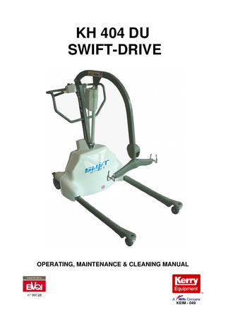
KH 404 DU SWIFT-DRIVE
OPERATING, MAINTENANCE & CLEANING MANUAL
KEIM - 049
INDEX PAGE
SPECIFICATIONS
2
SAFETY PRECAUTIONS
3
OPERATING INSTRUCTIONS
3
BATTERY CARE AND CHARGING
5
MAINTENANCE INSTRUCTIONS
5
CLEANING INSTRUCTIONS
7
SPECIFICATIONS DIMENSIONS:
Length 1100mm Internal Length 750mm Width 670mm Height 1220mm Effective lift range 430mm – 1700mm Leg gating (inside) 510mm – 885mm Leg gating (outside) 650mm – 1000mm Max height of C.S.P 1785mm Min Height of C.S.P 595mm Hoisting reach @ max height 600mm Hoisting reach @ min height 500mm Height of C.S.P at Max reach 1070mm Max reach 700mm Under base clearance 60mm Base height 210mm Leg height from floor 160mm Turning radius 1300mm
LIFT SPEED:
Slow - 38mm per second Fast - 58mm per second
LIFT DRY WEIGHT:
55 Kg (with batteries)
LIFT CAPACITY:
Max load - 150kg
CASTORS:
Ø150 Total lock rear polyurethane castor Ø75 Swivel front polyurethane castor Note: Smaller castors available on request.
FINISH:
Epoxy powder coated Polyurethane legs and yoke PVC cover
ELECTRICAL ITEMS:
Tested by Linak Australia to standards:- AS 3108-1990 - AS 3200.1-1990
KH404 DU
2
SWIFT DRIVE
SAFETY PRECAUTIONS. 1.
For safety precautions only properly trained personal should use the hoist. The KH 404DU Swift-Drive is manufactured and tested to handle a MAXIMUM safe working load of 150 Kg.
2.
The KH 404DU Swift-Drive is manufactured and tested with safety and function for the carer and patients as the utmost importance. No parts should be removed from the hoist without approval this may create an unsafe working condition.
3.
EMERGENCY STOP: The KH 404DU Swift-Drive is fitted with an emergency stop. This is the big red switch, located on the front of the controller. If there is a need to use this, simply depress the switch and it will automatically lock the position and cut all power to the electrical system. To disengage the emergency stop switch after it has been depressed, turn the red switch in a clockwise direction and the switch should return to its original position.
4.
EMERGENCY LOWERING AND RAISING. The emergency lowering/raising buttons can be used to lower/raise the lifter if there is an electrical or handset failure. The switches are located on the controller under the big red emergency stop switch. Simply press (using a ballpoint pen or similar object. DO NOT use a pin or compass) the button which you require. To halt the process, remove the pressure applied to the switch.
5.
LIFTING OF PATIENTS. For safety precautions only properly trained personal should use the lifter. When connecting the sling to the patient, please ensure the fitting instructions are adhered too. (Located on the sling or in the sling instruction brochure).
6.
Serial No., Model No., and Date of Manufacture are located on back cover.
7.
The hoist should not be used on rough or sloping surfaces. ie. Wheel chair ramps etc, and it is not recommended that the hoist be used outdoors.
8.
HOIST USAGE This hoist is designed to lift and transfer paitents from one area to another used in conjunction with the appropriate Kerry Equipment Sling. For further instruction consult the sling brochure supplied with your sling(s). 9.
While all care has been taken to eliminate all possible trap points on the hoist, there is potential for trapping your feet between the castors and legs, to avoid injury all personnel are to keep feet clear of this area during use.
10.
On a daily basis before using the hoist, check over for any damage, cracking etc. and for loose parts. This is to ensure safety for the hoist operator and patient.
KH404 DU
3
SWIFT DRIVE
OPERATING INSTRUCTIONS
Fig 4
1.1
HANDSET:
1.1a RAISE/LOWER: The SWIFT-LIFT operates via a touch pad hand controller. To raise or lower the hoist, simply press the required switch on the pad. (Fig 4) There are four switches on the hand controller for raising and lowering.
The top two switches are for slow normal operation (tortoise); the middle two switches are for faster operation (Hare). Simply choose the speed that suits your application.
1.1b LEG GATING: To OPEN or CLOSE the “Gate” on the legs, simply press the touch pad hand controller with the required function. (Fig 4 shows the lower set of switches that operate the leg “gate”). Open on the left, close on the right.
KH404 DU
4
SWIFT DRIVE
1.2
DRIVING:
To enable the DRIVE unit, operating procedures are as follows: 1. Insert key 2. Turn to ON 3. Push ON/OFF button, red light when on. 4. Turn speed knob to the required speed SLOW/FAST 5. Pull long lever UP onto underside of handle (lever must be enabled to operate) 6. Push paddle UP/REVERSE, DOWN/FORWARD
Red light flashes when charging is required.
Long lever Paddle
1.3
YOKE - SLING MOUNTING POINTS (Fig 5)
Refer to the fitting instructions supplied with your chosen sling.
Fig 5
KH404 DU
5
SWIFT DRIVE
BATTERY CHARGING AND CARE 1.
CHARGING
Before the KH 404 DU can be operated the batteries will need to be charged. Please follow the instructions below. 2.1 Plug the charger unit (Fig 6) into the 240-Volt supply outlet. Plug the charger into the recharge socket to start recharging (Fig 7) 2.2 The POWER ON LIGHT (RED) and CHARGING LIGHT (ORANGE) on the front of the charger will be displayed. The battery is fully charged when the GREEN LIGHT is on. NOTE: A battery pack may remain on charge indefinitely without any detrimental effects to the battery or charging unit.
Fig 6: Charger
Fig 7: Recharge socket 3.
BATTERY CARE
The KH 404 DU uses fully sealed lead acid batteries. Which are designed to be recharged on a regular basis. To care for your batteries and obtain the maximum life. DO NOT allow the batteries to run totally flat before recharging. The controller is fitted with an audio low battery warning alarm. When this warning alarm sounds complete the lift process, then change the battery and recharge. Kerry Equipment recommends that a 2-battery system be used; this allows one battery to always be on charge while the other is in use, and hence the hoist may never be out of service with a flat battery.
KH404 DU
6
SWIFT DRIVE
MAINTENANCE INSTRUCTIONS The KH404 DU hoist requires servicing at a recommended period of 6 monthly intervals to ensure optimal operation at all times. If the hoist is subject to large amounts of use, then it is recommended to have the hoist dismantled by a qualified service personnel and inspected for signs of wear at 2-year periods. This is dependant on use. In the unlikely event of fault or substantial wear contact your place of purchase or Kerry equipment directly.
LUBRICATION The KH 404 DU SWIFT-DRIVE require periodical lubrication. These points are: 1.
CASTORS It is always best practice to remove all hair and lint from the castors as soon as possible, always allowing free movement of all the wheels. The castors need to be lubricated monthly (Use TAC-2 only). This involves: -
1.1
The Castor head bearing will need lubricating. Simply spray TAC-2 up into the bearing while rotating the castor (Fig 7). The wheel also requires lubricating every month. To do this the wheel must be unbolted and removed from the castor frame. TAC-2 can then be sprayed into the hub centre to lubricate the internal bearings (Fig 8).
Fig 7 2.
Fig 8
BASE PIVOT POINTS
All pivot points will need to be lubricated with TAC-2 or similar lubricant. Simply spray for 2 seconds on each side of the recommended points monthly. The hoist has to be turned onto its side for access to the following lubrication points. (To do this 2 people are required.) Follow the instruction below: 2.0.1 Both people are to stand on one side of the hoist. One near the push handle, the other by the side of the hoist. 2.0.2
The person near the push handle locks the total lock castors.
2.0.3
In conjunction with one another pull the hoist towards the side, lowering the hoist onto its side on the floor.
2.0.4
The hoist can lie on its side without damage to the plastic cover, but care must be taken when lowering/raising.
You now have access to ALL the lubrication points. ie: pivot points, leg lever, leg pivot etc.
KH404 DU
7
SWIFT DRIVE
Simply spray TAC-2 on all the pivot points for 2 seconds. 2.1
Leg Actuator Pivots (Fig 9) Leg Pivots (Fig 9) Tie Rod Pivot Points (Fig 9) Fig 9
3.
ARM AND ACTUATOR PIVOT POINTS The arm pivot points will need to be lubricated with TAC-2 or similar lubricant. Simply spray for 2 seconds on each side of the recommended points monthly. 3.1
Arm Pivot (Fig 10) Actuator Pivots (Fig 10)
Fig 10 TAC-2 is a CRC product and is available from most automotive outlets or from Kerry Equipment.
KH404 DU
8
SWIFT DRIVE
TROUBLE SHOOTING/ASSISTANCE LIFTER & DRIVE UNIT NOT WORKING : Ensure batterys are fully charged Check that Emergancy stop button is not depressed Ensure key is at on position on hand control Ensure red light is on and depressed on hand control Check all visible connections Check for damage to handset or unit If problems still persist, please contact your nearest Kerry Equipment distributor or Kerry Direct on the details provided in the rear of this manual. Do not attempt to remove cover.
ASSEMBLY / DISASSEMBLY INSTRUCTIONS Kerry Equipment fully assembles their hoist prior to delivery. Kerry Equipment only recommends qualified service personal to work or service any of their hoists. Any assembly or disassembly should be checked with Kerry Equipment and or Distributor before commencing with any repair.
GENERAL CLEANING 1.
The KH 404 DU SWIFT-DRIVE can be cleaned with a low strength detergent, warm water and a soft textured cloth. This includes all Epoxy powder coated framework, PVC cover, polyurethane legs and yoke.
2.
CAUTION Do not immerse any parts in water. Do not allow water/cleaning liquid to enter the battery or controller. Clean up spills immediately.
3.
SLING CARE Protect from direct sunlight. Repair any cuts or fraying immediately. Slings are machine washable. Please refer to care instructions on the sling.
Distributed by: -
Rev. JAN 2006
KH404 DU
9
SWIFT DRIVE