Inmedico
Oscilla SM910-B User Manual
User Manual
13 Pages
Preview
Page 1
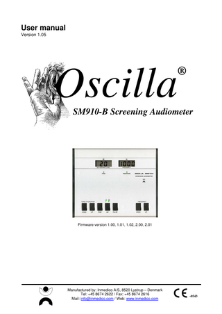
User manual Version 1.05
Oscilla
®
SM910-B Screening Audiometer
Firmware version 1.00, 1.01, 1.02, 2.00, 2.01
Manufactured by: Inmedico A/S, 8520 Lystrup – Denmark Tel: +45 8674 2622 / Fax: +45 8674 2616 Mail: [email protected] / Web: www.inmedico.com
-0543
User manual Oscilla® SM910-B
Table of contents 1
GENERAL DESCRIPTION... 3
2
DESCRIPTION OF FRONT PANEL ... 4
3
DESCRIPTION OF BACK PANEL... 5 3.1 3.2
4
HOOK-UP... 5 BATTERIES ... 5
OPERATION... 6 4.1 4.2 4.3 4.4 4.5
TONE ATTENUATOR... 6 TONE ... 6 AIR... 6 PULSE... 6 FREQUENCY ... 6
5
TECHNICAL SPECIFICATIONS ... 7
6
PLEASE REMARK ... 9 6.1 6.2 6.3 6.4 6.5 6.6 6.7
7
SAFETY PRECAUTION ... 9 PACKING GUIDANCE ... 9 CALIBRATION ... 9 CLEANING / DISINFECTION ... 9 PRODUCT WARRANTY... 9 PRODUCT LIFE ... 9 SYMBOLS ... 10
EMC... 11
Page 2 of 13
User manual Oscilla® SM910-B
1 General description OSCILLA® SM 910-S is a manual screening audiometer. The device is controlled by an advanced microprocessor, which makes it very quick and accurate to operate.
Function This device supports pure-tone and can perform screening hearing tests in order to determine the hearing ability of a person. Additionally it may operate with batteries and are thus location-independent and ultra-portable. Intended application The intended application of the device is to be used within a screening environment operated by trained health personal or likewise. Classification Type 4 - Screening Audiometer For additional information refer to the technical specifications on page 7.
Page 3 of 13
User manual Oscilla® SM910-B
2 Description of front panel
1
3
4
2
5
6
7
1 ISO hearing level - The actual sound pressure in dB 2 Frequency - The actual frequency in Hz 3 Tone attenuator - Push the DOWN/UP buttons to change attenuator 4 Tone - Sends tone to the patient 5 AIR - Determines whether the tone is going to the right/left ear 6 Pulse - Starts a pulsing tone with a modulation frequency of 2.5 Hz 7 Frequency - Pushing one of the buttons changes the frequency
Page 4 of 13
User manual Oscilla® SM910-B
3 Description of back panel 3.1 Hook-up Earphones and patient answer button is mounted with jacks, which fit into the connectors on the back of the device. Also, connection for mains-adapter is placed here. After having connected the above mentioned accessories and connected the adapter to a mains outlet, turn on the device by means of the ON/OFF button.
Frequency will be set on 1000 Hz and attenuator display on 20 dB. 3.2 Batteries In addition to the mains adapter, the audiometer may be operated on 6 AA size (LR6) batteries. These are placed inside the unit, behind the lid on the bottom of the unit. To access the battery compartment, unscrew the two screws that hold the lid, and insert or replace the batteries. Be careful to respect the polarity of the batteries, as shown inside the compartment. The life of the batteries can be expected to be approximately 50 hours of operation. When the batteries are running low on power, the audiometer will show a flashing LO BATT in the display, every 10th second. In this condition the unit may still be used for a while, but accurate sound pressure level can not be guaranteed. It is recommended to replace the batteries or switch to the mains adapter when the LO BATT message appears. You may operate the audiometer from the mains adapter at any time to save battery power, the batteries will be disconnected automatically when you insert the adapter plug.
Please note: If the unit is not in use for a long time, or always is operated from the mains adapter, it’s recommended to remove the batteries to avoid the risk of damage from leaking battery acid.
1
2
3
4
5
1 RIGHT – Right phone (red) 2 LEFT – Left phone (blue) 3 RESPONSE - Patient response button 4 ON/OFF – On/off switch 5 POWER – Power input from mains adapter
Page 5 of 13
User manual Oscilla® SM910-B
4 Operation 4.1 Tone attenuator By applying light pressure to the DOWN/UP buttons the attenuator steps up or down in 5 dB
The actual sound pressure can be read in the display
Holding down one of the buttons, the sound pressure is increased or decreased until the button is released. Increments: in the range from -10 dB to 90 dB (refer to max. intensities under Technical Specifications). 4.2 Tone With the interrupter button a tone is delivered to the patient.
4.3 AIR The output button determines whether the tone is going to the right or left ear.
The light will shine as long as the tone is present.
When the L (left) lamp is on, the tone is sent to the left ear.
Oppositely, the tone is sent to the right ear, when the R (right) light is on.
For each touch of the AIR key, ears are changed. 4.4 Pulse By pushing the PULSE button a pulsing tone with a modulation frequency of 2.5 Hz is emitted.
4.5 Frequency Pushing one of the buttons changes the frequency to the next fixed value.
One more push turns off this modulation.
The actual frequency can be read in the display
Page 6 of 13
User manual Oscilla® SM910-B
5 Technical specifications Standards compliance:
Audiometer TDH-39 sound pressure: Safety: Electromagnetic compliance: Medical Instrument Directive: (CE Mark)
Classification:
EN 60645-1, EN 60601-1, EN 60601-1-1, EN 60601-1-2 EN ISO 389-1 EN 60601-1:1990 + A1:1993 + A2: 1995 + A13:1996 EN 60601-1-2:2001 + EMC Directive 89/336/EEC MDD 93/43/EEC
Group 1, class B EN 60601-1-2:2002 Type of protection against electric shock:
Class I equipment
Degree of protection against electric shock:
Type B applied part
Degree of protection against liquid penetration: Degree of safety of application in the presence of flammable anaesthetics: Mode of operation:
IPO, ordinary equipment N/A Continuous operation
Medical CE- mark:
Inmedico A/S is approved for medical CE marking, by DGM. Identification number 0543
Transducers:
TDH-39 air conduction
Power Supply:
12 VAC, approx. 80mA max. or 6x AA (LR6) batteries.
Adaptor:
Primary: Secondary:
230 VAC, 50/60 Hz, 60mA max. 12 VAC, 7 VA, ± 10 %
Environmental Conditions for Operation Ambient Temperature: +15 to +35 degree Celsius. Relative Humidity: 30 % to 90 % Surrounding pressure: 80 kPa to 120 kPa
Environmental Conditions for Storage Ambient Temperature: -10 to +50 degree Celsius Relative Humidity: 95% or less (non-condensing) Surroundings pressure: 50 kPa to 120 kPa Physical Attributes Dimensions: Weight: Casing material:
225 (W) x 180 (D) x 55 (H) mm ~ 0,5 kg including accessories Aluminium
Calibration:
Data is saved in eeprom memory, EN 60604-1
Warm-up time:
< 3 seconds.
Included parts:
1 audiometer, 1 set of Peltor H7A headphones with TDH-39, 1 response button, 1 user manual, calibration certificate and 6 AA (LR6) batteries.
Page 7 of 13
User manual Oscilla® SM910-B Accessories:
carrying bag
Measurement specifications Measurement Method
Manual threshold test without storage of data.
Measurement Range Maximum Intensities:
Measurement Accuracy Tolerance frequency: In/output impedance: Distortion speaker: Single signal channel: Air conductor:
Frequency
Air
125 Hz 250 Hz 500 Hz 750 Hz 1000 Hz 1500 Hz 2000 Hz 3000 Hz 4000 Hz 6000 Hz 8000 Hz
50 dB 70 dB 90 dB 90 dB 90 dB 90 dB 90 dB 90 dB 90 dB 80 dB 70 dB
± 1 %. Left / Right channel ~ 4,7- 144,7 ohm, Patient response ~ 1 K ohm TDH-39: < 1 %, 4. and higher harmonic + sub harmonic < 0,3 %.
± 4 dB (125 Hz – 4 kHz) ± 5 dB (6 kHz – 8 kHz)
Page 8 of 13
User manual Oscilla® SM910-B
6 Please remark 6.1 Safety precaution Medical electrical equipment need special precautions regarding EMC and needs to be installed and put into service according to the EMC information provided in the accompanying documents. Portable and mobile RF communications equipment can affect medical electrical equipment. Interruptions of the mains adapter must be carried out on the outlet. If the audiometer / personal computer are exposed to a powerful static discharge, this can cause interruption of the signal without interruption of the device. Should this rare state occur? Turn the audiometer off and then on. Under normal conditions the device should function again. Neither the patient nor user will be exposed to any danger; likewise the calibrations settings or other functions would be affected. If a failure should occur, meaning the device is missing a function or has a fault, please contact the seller of the device or the manufacture. Repair of the device must be accomplished by Inmedico A/S or special trained persons with a given permission to repair the product. PC, printers or other equipment there are used together with the audiometer, must meet the specified demands there are given in standard EN60601-1 § 14.1a 6.2 Packing guidance By shipment, the device must be wrapped into bubble plastic and put into an ordinary export case. None of the audiometer parts must be able to touch the sides in the box. The audiometer withstand ordinary air freight and similar. 6.3 Calibration It’s recommended to get the device calibrated every 2nd year, by qualified personal.
6.4 Cleaning / disinfection Audiometer parts that are in contact with the patient include patient response and headset. Both can be cleaned with a cloth wrung in lukewarm water and a little soap. Disconnect both parts from the audiometer before cleaning and make sure they are dry before connecting them again.
6.5 Product Warranty 2 years – device only
6.6 Product Life 20 years - estimated
Page 9 of 13
User manual Oscilla® SM910-B 6.7
Symbols
AC - 12V alternating current
Caution
Type B, EN60601-1
Must be properly disposed
Page 10 of 13
User manual Oscilla® SM910-B
7 EMC Guidance and manufacture´s declaration – electromagnetic emission The SM910-B is intended for use in the electromagnetic environment specified below. The customer or the user of the SM910 should assure that it is used in such an environment.
Emissions test
Compliance
RF emissions CISPR 11
Group 1
RF emissions CISPR 11
Class B
Harmonic emissions
Complies
IEC 61000-3-2 fluctuations/flicker emissions
Complies
Electromagnetic environment - guidance The SM910-B uses RF energy only for its internal function. Therefore, its RF emissions are very low and are not likely to cause any interference in nearby electronic equipment.
The SM910-B is suitable for use in all establishments, including domestic establishments and those directly connected to the public low-voltage power supply network that supplies buildings used for domestic purposes.
IEC 61000-3-3
Page 11 of 13
User manual Oscilla® SM910-B
Guidance and manufacture´s declaration – electromagnetic immunity The SM910-B is intended for use in the electromagnetic environment specified below. The customer or the user of the SM910 should assure that it is used in such an environment.
Immunity test
Compliance level
Electromagnetic environment – guidance
± 6 kV contact
± 6 kV contact
± 8 kV air
± 8 kV air
Floors should be wood, concrete or ceramic tile. If floors are covered with synthetic material, the relative humidity should be at least 30 %.
Electrical fast transient/burst
± 2 kV for power supply lines
± 2 kV for power supply lines
IEC 61000-4-5
± 1 kV for input/output lines
± 1 kV for input/output lines
Surge
± 1 kV differential mode
± 1 kV differential mode
IEC 61000-4-5
± 2 kV common mode
± 2 kV common mode
Mains power quality should be that of a typical commercial or hospital environment.
Voltage dips, short interruptions and voltage variations on power supply input lines
<5 % UT (>95 % dip in UT) for 0,5 cycle
<5 % UT (>95 % dip in UT) for 0,5 cycle
Mains power quality should be that of a typical commercial or hospital environment.
40 % UT (60 % dip in UT) for 5 cycle
40 % UT (60 % dip in UT) for 5 cycle
70 % UT (30 % dip in UT) for 25 cycle
70 % UT (30 % dip in UT) for 25 cycle
If the user of the SM910 requires continued operation during power mains interruptions, it is recommended that the SM910 be powered from an uninterruptible power supply or a battery.
<5 % UT (>95 % dip in UT) for 5 sec
<5 % UT (>95 % dip in UT) for 5 sec
3 A/m
3 A/m
Electrostatic discharge (ESD)
IEC 60601 Test level
IEC61000-4-2
IEC 61000-4-11
Power frequency (50/60 Hz) magnetic field
Mains power quality should be that of a typical commercial or hospital environment.
Power frequency magnetic fields should be at levels characteristics of a typical location in a typical commercial or hospital environment.
IEC 61000-4-8
NOTE UT is the a.c. mains voltage prior to application of the test level.
Page 12 of 13
User manual Oscilla® SM910-B
Guidance and manufacture´s declaration – electromagnetic immunity The SM910-B is intended for use in the electromagnetic environment specified below. The customer or the user of the SM910 should assure that it is used in such an environment.
Immunity test
IEC 60601 Test level
Compliance level
Electromagnetic environment – guidance Portable and mobile RF communications equipment should be used no closer to any part of the SM910-B, including cables, than the recommended separation distance calculated from the equation applicable to the frequency of the transmitter Recommended separation distance
d = 1,17 P Conducted RF
3 Vrms
IEC 61000-4-6
150 kHz to 80 MHz
Radiated RF
3 V/m
IEC 61000-4-3
80 MHz to 2,5 GHz
3 Vrms
d = 1,17 P 80 MHz to 800 MHz 3 V/m
d = 2,33 P 800 MHz to 2,5 MHz Where P is the maximum output power rating of the transmitter in watts (W) according to the transmitter manufacturer and d is the recommended separation distance in meters (m). Field strengths from fixed RF transmitters, as determined by an electromagnetic site survey, a should be less than the compliance level in each frequency range b Interference may occur in the vicinity of equipment marked with the following symbol:
3
NOTE 1 At 80 MHz and 800 MHz, the higher frequency range applies. NOTE 2 These guidelines may not apply in all situations. Electromagnetic propagation is affected by absorption and reflection from structures, objects and people.
Page 13 of 13