INO Therapeutics
INOvent Pre-Use Checkout
Pre-Use Checkout
2 Pages

Preview
Page 1
INOvent Pre-Use Checkout ®
For details of this procedure reference the Operation and Maintenance Manual Section 5/ Pre-Use Procedure Important:
This guide is provided for general information only and is not a substitute for the Operation and Maintenance Manual. Refer to the manual for detailed information. 24 hour Technical Support Tel. 877.566.9466
Step I: High Pressure Leak Test Turn the INOvent delivery system ON and make sure the buzzer and speaker sound. Wait until monitor displays numeric values for NO/NO2/O2 (make sure manual bagging flowmeter is turned off). Perform high pressure leak test. Inspect all gas connections, verify the white plastic (Kel-F) tip, on the end of the regulator hose, is in place and not damaged. Connect the regulator to the INOmax® treatment cylinder and to the quick connect on the INOvent. Open and then close the INOmax cylinder valve. Monitor pressure gauge for 30 seconds for any signs of leakage. Repeat the process using the second regulator assembly. Note: The pressure drop leak test will not detect leaks at the cylinder valve outlet connection because of the check valve in the regulator hose. If a leak is suspected, see the O&M manual Section 13/ Appendix B.
Step II: Low Range Calibration
(refer to page 4-2 in the O&M Manual for details)
Perform Low Range Calibration.
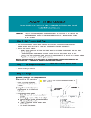
Step III: Purge Assemble connectors and tubing as shown in Diagram #1 for this procedure. Ensure the INOmax regulator is pressurized and the cylinder valve is closed.
Be sure a purge has been completed within five minutes before the start of NO therapy.
Using a flowmeter from the wall or a cylinder source, set the oxygen flow to 15 L/min. Purge INOvent Delivery System. Set the NO dose to its maximum concentration (80 ppm). Cylinder gauge pressure will drop slowly to 0 psi. Measured NO2 will increase, and then decrease as NO2 is purged from the system. "Low NO/N2 Pressure" and the "Delivery Failure" alarms will occur. The purge is now complete.
(Connected to wall/tank)
Diagram #1
Step IV: Performance Test Leave everything connected as in Diagram # 1 for this procedure. Open INOmax® cylinder valve. Using a flowmeter from the wall or a cylinder source, ensure the oxygen flow is set to 15 L/min. as in step 3. Set NO dose to 40 ppm, allow values to stabilize. Compare INOvent monitor values to the table below. Set NO Dose
40 ppm
Acceptable NO Values
32-48 ppm
Acceptable NO2 values
< 1.5 ppm
FiO2
95% ± 3%
(allow 2-3 minutes for monitored values to stabilize) If NO2 levels are greater than 1.5 ppm repeat the Purge Procedure as listed in step three and then repeat the Performance Test.
Step V: Manual NO Delivery Performance Assemble connectors and tubing as shown in Diagram # 2. Using the oxygen flowmeter on the INOvent, turn on flow to the manual bagging system to 15 L/min. observe the ball float rise on the front panel. Verify the monitored NO value is 20 ppm ± 8 ppm. Reduce the oxygen flow to 1 L/min and verify that the ball float on the INOvent drops.
Diagram #2
(INOvent - rear view)
DO NOT connect a high pressure (50 psi) oxygen source directly to the O2 inlet of the INOvent. Be sure to turn the O2 flow to the manual system off when not in use. 1 2 3 4 5 6 7 8 9
Inspiratory Gas Sample Line Oxygen tubing (user supplied) NO/O2 outlet O2 inlet O2 supply hose from the O2 flowmeter INOvent Pressure Compensated O2 flowmeter NO/N2 input hoses from the regulators 15M x 4.5 mm Adapter Sample Tee
(INOvent Flowmeter located on the side of the INOvent cart)
End of Pre-Use Check Out Typical System Connection Diagram (ICU Ventilator).
150-300mm (6'-12')
Provided courtesy of INO Therapeutics TS-PRD-0008 Rev. 4.0