IRadimed Corporation
iMagox MRI Pulse Oximeter Operation Manual rel 1C
Operation Manual
80 Pages
Preview
Page 1
iMagox
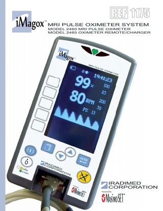
REF 1175 TM
MRI PULSE OXIMETER SYSTEM MODEL 2460 MRI PULSE OXIMETER MODEL 2465 OXIMETER REMOTE/CHARGER
IRADIMED CORPORATION Powered By
ImagoxTM MRI Pulse Oximeter System Model 2460 Pulse Oximeter and Model 2465 Remote/Charger Operation Manual, Part Number 1175 Release 1C, 2015-11 PER ECN 000721 © 2015 IRadimed Corporation
IRadimed Corporation 1025 Willa Springs Drive Winter Springs, Florida 32708 USA Tel 407-677-8022 Fax 407-677-5037 e-mail:customerservice@iradimed.com
European Authorized Representative Medical Device Consultancy 7 Pinewood Drive Ashley Heath, Market Drayton, Shropshire, UK, TF9 4PA www.medicaldeviceconsultancy.co.uk
Paragraph
1.0 1.1 1.2 1.3 1.4 1.5 1.6 1.7 1.8 1.9 1.10 1.11
1.12 1.13 1.14
1.15 1.16
1.17 1.18
1.19 1.20 1.21 1.22 1.23 1.24 2.0 2.1 2.2
CONTENTS
Page
Introduction, ImagoxTM Pulse Oximeter, Model 2460... 1-1 1.0.1 User Warnings and Precautions ... 1-1 Installation ... 1-4 Introduction ... 1-4 Unpacking the Oximeter ... 1-4 Preparing the Oximeter for Use... 1-4 1.4.1 Installing Battery... 1-4 Mounting on I.V. Pole ... 1-5 Operational Checkout of the Oximeter ... 1-5 Oximeter Storage ... 1-5 Remote Display Installation... 1-5 1.8.1 Charging Battery with the Remote/Display Charger. ... 1-6 Language Options ... 1-6 Product Structure ... 1-7 Product Description ... 1-7 1.11.1Front of the Oximeter ... 1-8 1.11.2Back of the Oximeter ... 1-9 1.11.3Front of the Remote Display/Charger...1-10 1.11.4Back of the Remote Display/Charger ...1-11 1120 MRI Power Supply...1-12 Controls ...1-13 1.13.1Front Panel Control Keys...1-13 Symbols, Displays, and Controls ...1-15 1.14.1SpO2 Symbols...1-15 1.14.2 Informational Display ...1-16 1.14.3 Displays ...1-16 Operator Verification ...1-18 Operating the 2460 Pulse Oximeter ...1-19 1.16.1Probe Set-up and Use...1-20 1.16.2Applying the Model 1170 Fiberoptic SpO2 Sensor ...1-20 1.16.3Verifying Operation of the 1170 Fiberoptic Sensor ...1-23 Probe Cleaning ...1-23 1.17.1Cleaning the 1170 Sensor and 1171 Sensor Grips ...1-23 SpO2 Alarms and Alerts...1-23 1.18.1Patient and Equipment-Related Alarms ...1-24 1.18.2Watchdog Alarms...1-24 1.18.3Reviewing, Setting, or Changing Alarm Limits ...1-24 SpO2 Menu Choices ...1-25 SpO2 Troubleshooting ...1-26 SpO2 Parts and Accessories ...1-28 SpO2 Testing Summary ...1-29 Specifications ...1-30 The Masimo Set® Principles of Operation...1-31 Battery Operation ... 2-1 Introduction ... 2-1 Inserting the Battery Pack ... 2-1
i
2.3 2.4 2.5 2.6 2.7 2.8 2.9
Charging the Battery Pack... 2-2 Removing the Battery Pack ... 2-2 Testing the Battery Pack ... 2-3 Battery Charge Indicator ... 2-3 Battery Low Indication... 2-3 Battery Power Gauge ... 2-4 Battery Care and Maintenance:... 2-4 2.9.1 Introduction. ... 2-4 2.9.2 1133 Battery Pack Maintenance Checkout Procedure ... 2-4 2.10 Battery Pack Replacement ... 2-4 2.11 Battery Pack Related Precautions ... 2-5
ii
FIGURES Figure Page 1-1 Front of 2460 Oximeter ... 1-8 1-2 Back of 2460 Oximeter ... 1-9 1-3 Front of 2465 Remote/Display Charger ...1-10 1-4 Rear of 2465 Remote/Display Charger ...1-11 1-5 Model 1120 MRI Power Supply...1-12 1-6 Front Panel Control Keys...1-13 1-7 ImagoxTM 2460 Pulse Oximeter Display ...1-16 1-8 Connecting the 1170 Fiberoptic Probe...1-20 1-9 Applying the 1170 SpO2 Sensor...1-22 1-10 Saturation Charting...1-32 2-1 Battery Installation ... 2-1 2-2 Battery Removal... 2-2 2-3 Battery Test ... 2-3 Table Page 1-1 SpO2 Alarm Limits ...1-19 Appendix A: Specifications ... A-1 Appendix B: Repair ... B-1 Appendix C: Warranty information ... C-1 Appendix D: Manufacturers Technical Declaration ... D-1 Appendix E: Accessories... E-1 Appendix F: 1119 I.V. Pole Parts Description and Assembly ...F-1
iii
General Information This document provides directions for using the Iradimed 2460 MRI Pulse Oximeter: • Features a compact, easy to use, Pulse Oximeter, safe for use in the MRI enviornment. • The Remote Display/Charger Unit allows for wireless ability to control the Oximeter from outside the MR Scanner. The system is designed for use in the following patient care areas: • MRI (0.2 to 3T systems). • MRI/Recovery/Radiology • Oximeter operable and safe in up to 3 Tesla (30,000 Gauss) magnetic field line. EMI Statement: This equipment generates, uses and can radiate radio frequency energy and, if not installed and used in accordance with the instructions, may cause harmful interference to other devices in the vicinity. However, there is no guarantee that interference will not occur in a particular installation. If this equipment does cause harmful interference to other devices, which can be determined by turning the equipment off and on, the user is encouraged to try to correct the interference by one or more of the following measures: 1. Reorient or relocate the receiving device. 2. Increase the separation between the equipment. 3. Connect the equipment into an outlet on a circuit different from that which the other devices(s) are connected. 4. Consult the manufacture or field service technician for help. Mains Disconnection Method: 2460 Oximeter: Disconnect power cord (1121) from Appliance Inlet on the side of the MRI power supply unit (1120). 2465 Remote/Charger Unit: Disconnect power cord (1121) from Appliance Inlet on the side of the MRI power supply unit (1120). Alternate Voltage/Export: For power cord plug types see local country distributor. Unit shipped in USA with US 3 pin power NEMA plug. 2460 EQUIPMENT CLASSIFICATION Classification according to IEC 60601-1 According to the type of protection against electrical shock:
Class I equipment and internally powered
According to the degree of protection against electrical shock:
Type CF (defibrillator-proof) equipment
According to the type of protection against harmful ingress of water:
Ordinary Equipment. IEC 60601-1-2.
According to the methods of sterilization or disinfection:
Non-sterilizable. Use of liquid surface disinfects only.
According to the mode of operation
Continuous operation
Equipment not suitable for use in the presence of flammable anesthetic mixture with air or with oxygen or nitrous oxide
v
About the Oximeter: Intended Uses The Iradimed Corporation's Imagox 2460 MRI Pulse Oximeter System is intended for general hospital or clinical use by medical professionals whenever it is required to monitor patients before, during, or after Magnetic Resonance Imaging (MRI) scans, functioning while either in a stationary or mobile position. The Pulse Oximeter can be used inside the MRI room mounted outside the 30,000 Gauss line (3 Tesla line), and with shielded magnets of field strength of 3.0 Tesla or less. This device is available for sale only upon the order of a physician or other related licensed medical professional, and not intended for any home use applications. The Pulse Oximeter is used to measure, display, and record functional oxygen saturation of arterial hemoglobin (SpO2) and pulse rate of adult, pediatric, and infant patients in an MR environment. Testing of the oximeter was performed in MR conditional environments at 1.5T and 3T. It is indicated for spot checking and/or continuous monitoring of patients who are well or poorly profused in the MRI. Features include: • Masimo Set® Technology • Special RF noise shielding enclosure. The Oximeter is equipped with a unique battery display that provides the clinician continuous monitoring of battery capacity available. This information is displayed when the instrument is turned on. Optional modes are easily accessed with the press of one key. A 2.4 GHz wireless link allows communication between the Oximeter and remote display. Qualified service personnel can configure many features of the Oximeter to meet specialized needs. Specific Oximeter menu screens may vary depending on software release being used. U.S. and International patents pending. References to “Masimo” in this manual shall imply Masimo Corporation. “Masimo” and “Masimo Set®” are registered trademarks of Masimo Corporation. This device is covered under one or more of the following U.S.A. patents: 5,758,644, 5,823,950, 6,011,986, 6,157,850, 6,263,222, 6,501,975 and other applicable patents listed at: www.masimo.com/patents.htm. Possession or purchase of this device does not convey any express or implied license to use the device with unauthorized sensors or cables which would, alone, or in combination with this device, fall within the scope of one or more of the patents relating to this device.
vi
Warnings/Precautions Federal Law in the U.S.A. restricts this device to sale by or on the order of a physician. This device is intended for use by trained medical professionals only. Refer all service to Iradimed Corporation Authorized Service Representatives. The 2460 MRI Pulse Oximeter has been specifically designed for operation inside an MRI Magnet Room, and is designed to operate normally in the presence of most frequently encountered electromagnetic interference in the MRI environment. Under extreme levels of interference, such as in close proximity to an electrosurgical generator, cellular telephone or a 2 way radio normal Oximeter operation may be interrupted. Avoid use of the Oximeter under these conditions. The Model 2465 Remote Display/Charger is intended for use in the MRI control room. Do not operate the 2465 Remote Display/Charger inside the MRI Magnet Room. For safe operation, use only Iradimed Corporation recommended MRIcompatible or MRI-safe accessories. The Alarm Sound Volume is adjustable for various clinical environments. Ensure the alarm sound level is appropriate for the use environment in the MRI so that it can be heard above the ambient noise level, especially during scanning. Product damage may occur unless proper care is exercised during unpacking and installation. Do not use the Oximeter or Remote if they appear damaged in any way. The battery should be charged before use. Battery may not be fully charged upon receipt. Connect Oximeter to AC power for at least nine (9) hours before placing the Oximeter into use. Always connect the Oximeter power supply or Remote Display/Charger to a properly grounded 3-wire power receptacle. If the quality of the earth grounding is in question, use battery power for the Oximeter. This equipment is not suitable for use in the presence of flammable anesthetic or other gases. Do not use this system in the presences of flammable gases. Arrange tubing, cords and cables to minimize the risk of patient or other equipment entanglement. To avoid patient injury, always respond to Oximeter or Remote Display/ Charger alarms immediately. The Oximeter contains materials which must be recycled, or disposed of properly. For proper disposal methods, contact your local sales representative or distributor. There are dangerous voltages present on internal components that may cause severe shock or death upon contact. Never open the oximeter casing, its power supply, or the Remote/Charger when connected to AC Mains power. Disconnect from AC power and remove battery pack prior to servicing or cleaning. Do not operate the oximeter on patients with the battery removed (oximeter will stop and not alarm during AC power loss without battery installed). Use of a properly maintained and charged battery will allow proper operation. Do not touch battery connector pins and patient simultaneously. vii
If the Low Battery alarm sounds, connect the oximeter with its power supply to AC power immediately. Replace blown fuses on the 1120 Pump MRI power supply or Remote Display/ Charger with fuses of the same type and rating only, or a fire hazard could exist. Never use sharp objects (paper clips, needles, etc.) to clean any part of the oximeter. Do not sterilize the oximeter or any component by heat, steam, ethylene oxide (ETO), or radiation. To avoid damage to the I.V. Pump and Pole, always move the I.V. Pole separately from the patient trolley to prevent accidental entanglement. Dropping, or a severe shock to the oximeter could result in damage and resultant oximeter inaccuracy. Refer the oximeter to qualified service personnel for proper checkout if either of these conditions occur.
viii
Battery Pack Related Warnings/Precautions The 1133 Battery Pack contains several lithium-polymer cells and an integral safety circuit. As these cells age, they can expand due to internal gas release, which is anticipated for this type of cell. However, if excessive expansion occurs, this can result in the battery case expanding (swelling), and possibly cause failure of the battery case, cells, or safety circuit. If this is observed, remove the Battery Pack from use and replace it as soon as possible. The 1133 Battery Pack contains protective circuitry to prevent catastrophic battery failure. If the Battery pack is damaged, this protective circuitry may not prevent battery failure. Remove the Battery Pack from use if the Pack becomes damaged, or the potential for Battery Pack damage is suspected. Do not use a damaged or swollen 1133 Battery Pack. Avoid damage to the 1133 Battery Pack by impact, dropping, overheating, or mechanical abuse. Never compress, drop, shock, or strike the 1133 Battery Pack. Never use objects that could puncture the internal battery cells. Any of these actions can cause the battery cells to heat, smoke, or cause catastrophic battery failure, which could result in fire. Do not attempt to disassemble the 1133 Battery Pack. Damage caused by disassembly or tool use can result in catastrophic battery failure, which could result in fire. If the 1133 Battery Pack case begins to expand and/or swell, discontinue battery charging and use immediately, and replace the Battery Pack. Continued charging will cause further Battery Pack case expansion, with possible battery case fracture, and potential electrolyte leakage. If the 1133 Battery Pack becomes damaged, avoid contact with the battery cell electrolyte. If the electrolyte contacts the skin or eyes, seek medical attention immediately. If the 1133 Battery Pack shows sign of the battery case expanding (swelling), remove the Battery Pack from use and replace it as soon as possible. In extreme conditions, this swelling can cause the 1133 Battery Pack to become jammed or stuck within the 2460 Oximeter or 2465 Remote Display, and/or cause the Battery Pack plastic case to burst open. If this occurs, do not use tools that could cause damage to the internal battery cells. Under no circumstances should Battery Packs or the internal cells be incinerated as this can cause an explosion.
ix
Pulse Oximeter Related Warnings/Precautions USE ONLY Recommended SpO2 Fiberoptic Sensors (Sensors containing
electrical conductors will cause patient burns). Do not use cables or sensors that contain conductive wires. This device is intended only as an adjunct device in patient assessment. It must be used in conjunction with other methods of assessing clinical signs and symptoms. Iradimed SpO2 sensors are reverse gender connectors (female connector on sensor cable / male connector on Oximeter) than that found with other nonMRI pulse oximeters. This is done to help prevent improper sensor connection to the Oximeter. Use only recommended pulse oximeter sensors. These sensors are manufactured to meet the accuracy specifications for Iradimed Corporation’s pulse oximeters. Using other manufacturers’ sensors can result in improper pulse oximeter performance. The fiberoptic cable for this device is extremely sensitive and must be handled with caution at all times. DO NOT use a damaged sensor. Refer to the User Warnings and Precautions area in Section 1 for additional Pulse Oximeter related warnings and precautions.
x
User Responsibility This product will perform in conformity with the description contained in this users manual and accompanying labels, inserts, etc., when assembled, operated, maintained and repaired in accordance with the instructions provided. This product must be checked and calibrated periodically. A malfunctioning product should not be used. Parts that are broken, missing, plainly worn, distorted or contaminated should be replaced immediately. Should such repair or replacement become necessary, refer unit to Iradimed Corporation qualified service personnel. This product or any of its parts should not be repaired other than in accordance with written instructions provided by the manufacturer, or altered without written approval of Iradimed Corporation. The user of the product has the sole responsibility for any malfunction which results from improper use, faulty maintenance, improper repair, damage or alteration by anyone other than Iradimed Corporation or Iradimed Corporation authorized service personnel.
Using This Manual Read this manual completely before attempting to use the Oximeter. Warning, Cautions and Notes. This manual contains three levels of precautionary information. • A Warning alerts the user that there is a possibility of injury or death to a human being. • A Caution alerts the user that there is a possibility of damage to equipment. • A Note contains essential information deemed especially important by Iradimed Corporation.
Definitions BPM %SpO2
Pulse Rate in Beats per minute. Percent of Oxygen (pulse) Saturation.
xi
Symbols
BPM
Attention: Consult Accompanying Documents.
Appropriate for use in MR environment
Defibrillator proof Type CF Applied Part
MR Conditional. Only appropriate for use in MR environment with manufacturer’s defined restrictions.
Date of Manufacture
MR Unsafe. Not appropriate for use in MR environment (i.e. inside the MR magnet room)
Indicates that the device conforms to the Medical Device Directive
Product Serial Number
Product Part Number
Alternating Current
Main Battery Capacity. (X inside Icon denotes no battery installed.)
Direct Current
AC Power is connected to 100-240 VAC
Pulse Detected
Percent of Oxygen (pulse) Saturation
Power On, or On
Pulse Rate in Beats/Minute
Power Off, or Off
Maximum rated load is 20 Kg.
Input/output connection. Allows data communication.
Telecommunications Alert Symbol Class 2 (European Union Countries Only)
Input Connection Only
Contains Lithium. Requires proper disposal/recycling of this material.
Radio-Frequency transmission source
Spare Battery Capacity. (X inside Icon denotes no battery installed.)
2.4 GHz Radio Antenna
EC Authorized Representative
2.4 GHz Radio is communicating.
This product has been certified to UL60601-1 and applicable Particular Standard IEC 60601-2-24, for which the product has been found to comply by Intertek.
xii
Output Connection Only
SECTION 1 PULSE OXIMETER 1.0
Introduction, ImagoxTM Pulse Oximeter, Model 2460.
The ImagoxTM 2460 Pulse Oximeter System includes a Digital Pulse Oximeter for use in simultaneously measuring and displaying functional oxygen saturation of arterial hemoglobin (SpO2) and pulse rate of adult, pediatric and infant patients in an Magnetic Resonance (MR) environment. For this measurement, testing was performed in MR conditional environments at 1.5T and 3T. It is intended for spot checking and/or continuous monitoring of patients who are well or poorly perfused. Informational tones communicate important information. Informational tones includes the pulse rate tone (which changes in pitch with SpO2 values: higher tones for higher SpO2, and lower tones for lower SpO2). References to “Masimo” in this manual shall imply Masimo Corporation. “Masimo” and “Masimo Set®” are registered trademarks of Masimo Corporation. 1.0.1 User Warnings and Precautions. IMPORTANT: The SpO2 function turns off when the Sensor Fail or No Probe message is displayed and the Alarm has been silenced. To re-activate the SpO2, plug-in a working SpO2 probe. Warnings • USE ONLY Recommended SpO2 Fiberoptic Sensors (Sensors containing electrical conductors will cause patient burns). Do not use cables or sensors that contain conductive wires. • This device is intended only as an adjunct device in patient assessment. It must be used in conjunction with other methods of assessing clinical signs and symptoms. • Pulse rate measurement is based on the optical detection of a peripheral flow pulse and therefore may not detect certain arrhythmias. The pulse oximeter should not be used as a replacement or substitute for ECG based arrhythmia analysis, or as an apnea monitor. • A pulse oximeter should be considered an early warning device. As a trend towards patient deoxygenation is indicated, blood samples should be analyzed by a laboratory co-oximeter to completely understand the patient's condition. • Pulse oximeters require detection of a valid pulse to correctly determine SpO2 and Pulse Rate values. This oximeter contains both audible and visual pulse indicators. The pulse waveform should be used an an indication of interference. Normal (noise free) waveforms will appear as a smooth rhythmic waveform pattern. • A "PROBE OFF" alarm or other alarms may not always indicate SpO2 sensor dislodgement. Use the SpO2 pulse waveform and other indicators to confirm proper SpO2 operation and sensor placement. 1-1
• Use only recommended pulse oximeter sensors. These sensors are manufactured to meet the accuracy specifications for Iradimed Corporation’s pulse oximeters. Using other manufacturers’ sensors can result in improper pulse oximeter performance. • As with all medical equipment, carefully route patient cables and connections to reduce the possibility of entanglement or strangulation. • To comply with relevant product safety standards, ensure that all alarm volumes are set appropriately and are audible in all situations. Do not cover or otherwise obstruct any speaker openings. • Sensor should be shielded from excessive extraneous incident light sources. Such extraneous light can cause reading error or pulse detection error. • When audible alarms cannot be heard due to ambient noise, visible alarms must be used. • The MRI SpO2 Sensor uses a glass-fiber cable, which can become damaged with rough handling. The fiberoptic cable for this device is sensitive and must be handled carefully at all times. Do not use a damaged sensor. Do not flex or bend the cable at extreme angles to avoid breaking fiberoptic strands within the cable. Use proper care to not pinch or step on the cable. Take care to loop cable neatly for storage, as all bends should have larger than a 3 inch (7.5 cm) radius. Do not attempt to disconnect the fiberoptic cable from the Sensor's connector shell. • The connector that attaches to the monitor must be kept outside the 10,000 Gauss line (or 1 Tesla magnetic field line) of the MR field and firmly secured to the monitor. • The SpO2 monitor can be used during defibrillation, but the readings may be inaccurate for a short time. Precautions • This equipment complies with IEC 60601-1-2:2001 for electromagnetic compatibility for medical electrical equipment and/ or systems. This standard is designed to provide reasonable protection against harmful interference in a typical medical installation. However, because of the proliferation of radio frequency transmitting equipment and other sources of electrical noise in healthcare and other environments, it is possible that high levels of such interference due to close proximity or strength of a source might disrupt the performance of this device. Medical electrical equipment needs special precautions regarding EMC, and all equipment must be installed and put into service according to the EMC information specified in this manual. • Portable and mobile RF communications equipment can affect medical electrical equipment. • If this device fails to respond as described, discontinue use until the situation is corrected by qualified technical professionals. • The sensor might not work on cold extremities due to reduced circulation. Warm or rub the finger to increase circulation, or reposition the sensor. • Do not gas sterilize or autoclave this device, sensors, or accessories. • Do not immerse the SpO2 patient cables in water, solvents, or cleaning solutions (the patient cable connectors are not waterproof).
1-2
• This device has motion tolerant software that minimizes the likelihood of motion artifact being misinterpreted as good pulse quality. In some circumstances, however, the device may still interpret motion as good pulse quality. • Inspect the sensor application site frequently at least every 1 hour to ensure correct sensor alignment and skin integrity. Patient sensitivity to sensors, sensor grips, and/or other methods may vary due to medical status or skin condition. • Never use probe extender cables with a fiber optic sensor. • Maximum SpO2 probe temperature is dependant on skin temperature. No active heating of the probe can occur during use. • Do not use caustic or abrasive cleaning agents on the unit or sensors. • Follow local, state and national governing ordinances and recycling instructions regarding disposal or recycling of the device and device components. • To prevent potential loss of monitoring or inaccurate data, remove any objects that might hinder pulse detection and measurement (e.g. blood pressure cuffs). • This device is designed to determine the percentage of arterial oxygen saturation of functional hemoglobin. Factors that may degrade pulse oximeter performance or affect the accuracy of the measurement include the following: - the SpO2 sensor attachment is too tight. - the patient is in cardiac arrest or is in shock. - excessive ambient light - excessive motion - electrosurgical interference - blood flow restrictors (arterial catheters, blood pressure cuffs, infusion lines, etc.) - moisture in the sensor - improperly applied sensor - incorrect sensor type - poor pulse quality - venous pulsations - anemia or low hemoglobin concentrations - cardiogreen and other intravascular dyes - carboxyhemoglobin - methemoglobin - dysfunctional hemoglobin - artificial nails or fingernail polish - a sensor not at heart level. • A functional tester cannot be used to assess the accuracy of a pulse oximeter monitor or sensor. • Operation of this device below the minimum amplitude of 0.3% modulation may cause inaccurate results.
1-3
• Review all Alarm limits to ensure they are appropriate for the patient. • Use the MRidium SpO2 Sensor Grips to attach the probe to the patient. Do not use tape to secure the probe to the patient. Examine the sensor site at routine intervals to prevent any possible pressure damage or tissue necrosis during longer term monitoring sessions. 1.1 1.2
1.3
Installation. Introduction. The 2460 ImagoxTM Pulse Oximeter has been designed for the monitoring of patients undergoing magnetic resonance imaging. Unpacking the Oximeter. Remove the oximeter and all accessories from their shipping carton and examine for visible damage that may have occurred during shipping. Check the materials carefully against the packing list and purchase request. Save all the packing materials, invoice and bill of lading as these may be required to process a claim against the carrier if there is damage from shipment. Contact Iradimed Corporation Customer Service for prompt assistance in resolving shipping problems.
The following is a list of items shipped with the 2460 Imagox Pulse Oximeter: • ImagoxTM 2460 MRI Pulse Oximeter. • ImagoxTM 2465 Remote Display/Charger. • ImagoxTM 1175 Operations Manual. • ImagoxTM 1176 Service Manual CD. • ImagoxTM 1133 Battery Pack. • Battery Charger/AC Adapter and Interconnect Cable. • Hospital Grade Power Cords. • Iradimed 1170 Fiber Optic SpO2 sensor • 2.4 GHz Antenna (for Wireless Remote) 1.4 Preparing the Oximeter for Use. Once the Oximeter and Remote have been unpacked, perform the following to prepare the oximeter for use. 1.4.1 Installing Battery. Slide the removable battery pack down into the rectangular open slot on the top rear of the ImagoxTM 2460. The battery pack will lock into place. a. Battery Initial Charging. The battery should be allowed to charge for nine (9) hours prior to placing the oximeter into use. The battery charges whenever the oximeter is connected to a hospital grade power outlet through the AC Power Adapter.
CAUTION: Use only a non-magnetic I.V. pole designed for proper safe
support of the Imagox 2460 MRI Pulse Oximeter (Iradimed model 1119 I.V. pole is recommended)
1-4
1.5 Mounting on I.V. Pole. The Oximeter should be mounted on an MRIcompatible (non-magnetic) I.V. pole and secured with its ergonomically designed clamp knob. The clamping mechanism accommodates pole diameters 1 to 1.5 inches (25 to 38 mm).
WARNING: When using multiple Oximeters (limit 2), distribute the Oximeters to ensure stability.
1.6 Operational Checkout of the Oximeter. Power up oximeter as follows and confirm no failures are displayed during the Power Up Test. a. Turn on oximeter. b. Observe while oximeter performs power up test. c. Verify that the oximeter sounds an audible beep. d. Observe that the oximeter displays the initial start-up screen. e. Attach 1170 SpO2 sensor as described in 1.16.2 and create a low SpO2 alarm, and verify a visual and audible alarm occur. 1.7 Oximeter Storage. Plug the oximeter into an AC outlet during storage to ensure a fully charged battery when needed. The AC indicator light will be green or amber (if charging) whenever oximeter is plugged in to the AC Power. 1.8 Remote Display Installation. Information shown on the Remote Display is updated at least once per second when communicating with the ImagoxTM 2460 monitor. Connect 2.4 GHz antenna and AC Power Cord to Remote Display/Charger and perform the following: a. Turn both 2460 Oximeter and 2465 Remote Display/Charger on. b. Press the Menu key on the Remote Display/Charger c. Press the NEXT MENU soft key to bring up additional menu options, then press the Set Comm Channel soft key. d. From the Radio Channel menu, select the desired Channel 1 through 5 by pressing the soft key next to that channel and verify that Channel is now highlighted. e. f. g. h.
Press the Menu key on the ImagoxTM 2460 MRI Oximeter. Press the NEXT MENU soft key to bring up additional menu options, then press the Set Comm Channel soft key. From the Radio Channel menu, select the same Channel that was selected for the Remote by pressing the soft key next to that channel and verify that Channel is now highlighted. Apply an ID marker to both the Remote and oximeter indicating the Channel selected if more than 1 oximeter is in use.
1-5
i.
Verify communication between Remote and Oximeter by pressing the Menu key on one and the Enter key on the other, and observing both display match and change simultaneously.
WARNING: Never Set two oximeters or two Remotes on the same Communication Channel. Always confirm the Remote Display is communicating with the selected oximeter before use.
1.8.1 Charging Battery with the Remote/Display Charger. If a spare battery is to be charged, insert battery into the Remote Display/Charger’s battery bay. Verify spare battery Icon is visible on the Remote Display/Charger’s informational display area. The AC/Power LED on the bottom, left-hand side will be amber colored until the battery is fully charged. The LED will turn green when battery is fully charged and the spare battery Icon in the Remote Display/Charger’s informational display area will be full with 4 bars.
CAUTION: Gently position 1133 battery pack into charger compartment
until battery pack snaps into position. Do not drop or force the battery pack into the charger compartment, as this could cause battery pack damage or failure. NOTE: If communication between Remote and oximeter is lost the Remote will sound a low pitched alarm for approximately 10 seconds. If communication is not returned after 10 seconds the Remote will sound a ramping high pitch alarm tone and display “No Communications.” 1.9 Language Options. The ImagoxTM System is capable of displaying information in languages other than English. This feature is service selectable, and should only be changed by qualified service personnel, as described in the 1176 Service Manual.
1-6
1.10 Product Structure. The ImagoxTM 2460 MRI Pulse Oximeter system mainly consists of the following:
1.11 Product Description. The ImagoxTM 2460 MRI Pulse Oximeter system is designed for operation in the MRI environment and may be used on the patient near the MRI magnet (up to the3.0 Tesla or 30,000 Gauss Line). Operating on battery power, when fully charged this system will provide up to 18 hours of operation. The 2465 ImagoxTM Wireless Remote Display allows for remote ability to control the Model 2460 MRI Pulse Oximeter from outside the MR Scanner. It utilizes the same user interface as the 2460 Oximeter and will allow adjustment of all Oximeter parameters and resetting alarms. The large clear display shows all Oximeter information at your desk top from the control room. The Wireless remote also acts as a charger for a backup or spare battery pack for the ImagoxTM 2460 MRI Pulse Oximeter. It utilizes a wireless link at 2.4 GHz for easy installation with no image artifacts. NOTE: The 2460 Oximeter will only communicate with 2465 wireless Remote/Display units. NOTE: The Remote Display/Charger only operates on AC Mains Power. This unit does not operate on battery power. This unit does not sound a Low Battery alarm for the Spare Battery being charged.
1-7