MEDRAD
Vistron CT Injection System Operation Manual Rev D Dec 2007
Operation Manual
71 Pages
Preview
Page 1
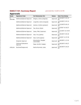
95403-T-141: Summary Report
generated Dec 14,2007,2:43 PM
Labeling Specification, 95403-T-141, Rev:D - Prior to use, you are responsible to confirm that this revision is the latest released revision and to verify accuracy of printed content.
Approvals Route
Signature/Task
Full Name(User ID)
Status
Date Time Stamp
R0001580
Additional/Optional Approval
Shigeno, James (shigenjh)
Approved
12/10/2007 3:42:10 PM
Additional/Optional Approval
Longinotti, James (longinjd)
Approved
12/14/2007 2:43:10 PM
Additional/Optional Approval
Jackson, Cristina (jacksocl)
Approved
12/13/2007 8:40:15 AM
Additional/Optional Approval
Fazi, Bruno (fazib)
Approved
12/4/2007 10:30:57 AM
Additional/Optional Approval
Casey, Mike (caseymp)
Approved
12/12/2007 10:19:09 AM
Additional/Optional Approval
Jack, Troy (jackta)
Approved
11/30/2007 3:55:28 PM
Additional/Optional Approval
Gaul, Curtis (gaulcj)
Approved
12/6/2007 11:37:38 AM
Originator Approval
Schumacher, Douglas (schumada)
Approved
11/30/2007 1:17:45 PM
Technical Publications Approval
Rapp, Jennifer (rappja)
Approved
11/30/2007 2:49:27 PM
ReviewedToApproved
Rachul-Rymniak, Linda
Approved
11/30/2007 9:18:24 AM
LifeCycle
1 of 71
Labeling Specification, 95403-T-141, Rev:D - Prior to use, you are responsible to confirm that this revision is the latest released revision and to verify accuracy of printed content.
TM
I N J E C T I O N
95403-T-141 Rev. D S Y S T E M
Operation Manual VOM 600E
2 of 71
Labeling Specification, 95403-T-141, Rev:D - Prior to use, you are responsible to confirm that this revision is the latest released revision and to verify accuracy of printed content.
MEDRAD TM
Vistron CT Injection System
Operation Manual
VOM 600E Rev. C 95403-T-141
3 of 71
Labeling Specification, 95403-T-141, Rev:D - Prior to use, you are responsible to confirm that this revision is the latest released revision and to verify accuracy of printed content.
Medrad addresses, phone and fax numbers: North America Headquarters MEDRAD Service Department One Medrad Drive Indianola, PA 15051-0780 U.S.A. Tel: Fax:
412 -767-2400 412 -767-4126
European Headquarters MEDRAD Europe B. V. Postbus 3084 6202 NB Maastricht The Netherlands Tel:
+31- 0 - 43 3585600
Fax:
+31- 0 - 43 3650020
Copyright 2007 Medrad, Inc. All rights reserved. Printed in USA. MEDRAD, Qwik-Fit Syringe and FluiDot are registered trademarks of Medrad, Inc. Medrad Vistron CT is a trademark of Medrad, Inc. The Medrad Vistron CT Injection System and related syringes are the subject of the following U.S. patents: 4,677,980 and 5,383,858. 4 of 71
Labeling Specification, 95403-T-141, Rev:D - Prior to use, you are responsible to confirm that this revision is the latest released revision and to verify accuracy of printed content.
Contents
Introduction ... 1 Important safety notice ... 1 Understanding symbols ... 1 Certifications ... 3 Indications for use ... 3 Contraindications ... 3 Restricted sale ... 3 Warnings ... 3 Cautions ... 4 Minimizing extravasation ... 4
Learning about the Medrad Vistron CT Injection System ... 7 Control panel ... 9 Programming controls ... 9 Injector head power control ... 9 Injector head controls ... 9 Arm/inject/disarm controls ... 9 Injector and Qwik-Fit Syringe disposable ... 10 Remote monitor ... 10 System power console ... 11
Preparing the injection system ... 13 Turning on the injector ... 13 Installing the Qwik-Fit Syringe disposable (125 and 200 ml) ... 13 Retracting the piston and installing the syringe ... 13 Filling the syringe ... 14 Expelling air and attaching the connector tube ... 16 Using a syringe heater ... 17 Reinstalling a syringe ... 17 Bracco Prefilled Syringe Installation ... 18
Setting up an injection protocol ... 21 Defining injection protocols ... 21 Setting the phase values ... 21 Selecting the phase ... 21 Setting the flow rate value ... 22 Setting the volume ... 23 Setting the duration value ... 23 Setting the Scan Delay timer ... 23 Setting the protocol’s pressure limit value ... 24 Viewing a protocol’s summary values ... 25 Deleting a protocol ... 25
Arming and injecting ... 27 Preparing to arm the injector ... 27 Arming the injector ... 28 Preparing to inject ... 28 Injecting ... 29 Recognizing pressure limiting conditions ... 29 Pausing an injection ... 30 Medrad Vistron CT Injection System
i
Operation Manual
5 of 71
Contents, continued Disarming or resetting the injector ... 30 Cleaning up the injector system after an injection ... 31 Putting the injector in standby mode ... 31 Cleaning the injector system ... 31 Storing the injector system ... 31
Labeling Specification, 95403-T-141, Rev:D - Prior to use, you are responsible to confirm that this revision is the latest released revision and to verify accuracy of printed content.
Appendix A: System Messages ... 33 Defining the message codes ... 33 U message code descriptions ... 33 P message code descriptions ... 34 d message code descriptions ... 34 C message code definitions and troubleshooting ... 34 Other malfunctions ... 35
Appendix B: Specifications ... 37 Injector head dimensions ... 37 Injector head pedestal dimensions ... 37 Remote monitor dimensions ... 38 System power console dimensions ... 38 Medrad Vistron CT Injection System capabilities ... 39 Forward/reverse piston motion controls ... 40 Syringe heater ... 40 EMI/RFI ... 40 Protection against electrical shock ... 40 Electrical requirements ... 40 Electrical leakage ... 40 Ground continuity ... 40 Environmental specifications ... 40 Protection against ingress of fluids (fluid entry)... 41 Mode of operation ... 41 Response to occlusions ... 41 Over and under infusion protection ... 41
Appendix C: Service, Maintenance and Contacting Medrad ... 43 Servicing the injector ... 43 Maintenance ... 43 Daily ... 43 Monthly ... 45 Annually ... 45 Operation check procedure ... 45 Contacting Medrad ... 46
Appendix D: Cleaning the injection system ... 49 Appendix E: System accessories ... 51 Appendix F: Installation ... 53 Mounting and removing the injector head ... 55 Mounting the remote monitor ... 55
Appendix G: Installation & Operation of AutoLink ... 57
Medrad Vistron CT Injection System
ii
Operation Manual
6 of 71
Labeling Specification, 95403-T-141, Rev:D - Prior to use, you are responsible to confirm that this revision is the latest released revision and to verify accuracy of printed content.
Introduction
Read the information contained in this section. Understanding the information will assist you in operating the device in a safe manner.
Important safety notice This device is intended to be used by individuals with adequate training and experience in computed tomography studies.
Understanding symbols The following symbols are used on the Medrad Vistron CT Injection System and components. Symbol
Description Attention, consult accompanying instructions. Indicates that this device conforms to the requirements of the European Medical Device Directive 93/42/EEC. Identifies the equipotential ground. Identifies the earth ground. Identifies the On switch position. Identifies the Off switch position. Indicates hazardous voltages. Indicates alternating current. Identifies a type BF applied part complying with EN 60601-1 standards.
CLASS 1
Indicates the injection system is Class 1 medical equipment as defined by EN 60601-1 standards.
Identifies connection of the injector head cable. Identifies the connection of the remote monitor. Identifies the Standby key. Identifies the connection on the injector head for the syringe heater.
Medrad Vistron CT Injection System
1
Operation Manual
7 of 71
Introduction, continued Understanding symbols, continued Symbol
Description
IPX1
Identifies the degree of protection against fluid as drip proof.
Labeling Specification, 95403-T-141, Rev:D - Prior to use, you are responsible to confirm that this revision is the latest released revision and to verify accuracy of printed content.
Identifies connection of the remote Start/Hold switch. Identifies the Fill Select key. Identifies the Autofill key. Identifies the Retract key. Identifies rotation direction on the manual knob for manually moving the piston. Clockwise is forward movement. Identifies the Start key. Identifies the Hold key. Identifies the Summary key. Identifies the Up Arrow key. Use to increase values when programming. Identifies the Down Arrow key. Use to decrease values when programming. J302
Identifies the AutoLink connector.
Identifies the power cord connector.
Additional symbols used in this manual indicate information that will assist you in operating this device in a safe and successful manner: Symbol
4
Description
Warning
Indicates that the information is a warning. Warnings advise you of circumstances that could result in injury or death to the patient or operator. Read and understand the warnings before operating the injector system.
Caution
Indicates that the information is a caution. Cautions advise you of circumstances that could result in damage to the device. Read and understand the cautions before operating the injector system. Indicates that the information that follows is a tip that will help you recover from an error or point you to related information within the manual.
Medrad Vistron CT Injection System
2
Operation Manual
8 of 71
Introduction, continued Certifications This device is equipped to operate at 100-240 VAC, 50/60 Hz, and is designed to be in compliance with EN 60601-1 (safety), EN 60601-1-2 (EMC/ Emissions).
Labeling Specification, 95403-T-141, Rev:D - Prior to use, you are responsible to confirm that this revision is the latest released revision and to verify accuracy of printed content.
Medrad, Inc., is ISO 9001/EN 460001 certified. Medrad Europe B.V. is EN-ISO 90002/EN 46002 certified.
Indications for use The device is designed specifically for the injection of intravenous contrast media into humans for diagnostic studies in computed tomography (CT) applications.
Contraindications This device is not to be used for drug infusion, chemotherapy, or any other use for which the device is not indicated. This device is not for portable use.
Restricted sale Federal (USA) law restricts this device to sale by or on the order of a physician.
Warnings •
Patient injury may result from a system malfunction. If a system malfunction occurs, immediately turn the injector off and disconnect the injector from the patient. If a fault message is displayed that cannot be corrected, and/or the injector is not operating correctly, do not use the injector. Call MEDRAD for assistance. (See Appendix C, Service and maintenance.)
•
Patient injury could result from leaks or ruptures during an injection. To prevent leaks or ruptures, use only catheters and connectors with pressure ratings compatible with this system. Always program the pressure limit lower than the pressure ratings of the catheters and connectors. This will help prevent leaks or ruptures in the event of a blockage.
•
Explosion hazard. Do not use the injector in the presence of flammables (such as anesthetics).
•
Unsafe operation may result from using improper accessories. Use only accessories and options provided by MEDRAD designed for this system.
•
Patient or operator injury can occur from a falling injector head or pedestal. Do not move the head, pedestal, or counterpoise system by pulling on the injector head or cabling. Move the injector by grasping the center of the pedestal or vertical arm on the counterpoise.
Medrad Vistron CT Injection System
3
Operation Manual
9 of 71
Introduction, continued
Labeling Specification, 95403-T-141, Rev:D - Prior to use, you are responsible to confirm that this revision is the latest released revision and to verify accuracy of printed content.
Cautions •
Injector may disarm or fail to operate when exposed to high magnetic fields. Do not use radio transmitters, cellular phones, or devices generating electrostatic discharge in the vicinity of this system.
•
Condensation may cause electrical damage to the injector. Do not use the injector immediately after it has been brought indoors from extreme outside temperatures. Allow the injector to stabilize at room temperature before use.
•
Injector damage can occur as a result of incorrect voltage. Before plugging in the injector, check the following:
•
–
Verify that the voltage and frequency marked on the serial tag on the back of the injector matches the voltage and current of the electrical outlet.
–
Verify that the injector has the appropriate power cord plug for the power outlet.
Injector electronic assemblies contain potentially hazardous materials. Dispose of system components or accessories properly. Follow local regulations for proper disposal or contact MEDRAD Service for assistance.
Additional warnings, cautions, and notes are located throughout this manual, where applicable.
Minimizing extravasation As a manufacturer, Medrad, Inc. cannot recommend specific procedures for venipuncture in enhanced computed tomography. We offer this compilation of information, obtained from the following physicians, as suggestions relating to practices which have worked well at their institutions. Richard L. Baron, M.D. Elliot K. Fishman, M.D. Robert Zeman, M.D. Philip Costello, M.D. Patrick Freeny, M.D. Paul M. Silverman, M.D. W. Dennis Foley, M.D.
University of Pittsburgh Medical Center Johns Hopkins Hospital Georgetown University Hospital New England Deaconess Hospital University of Washington Georgetown University Hospital Medical College of Wisconsin
Extravasation can be greatly reduced when proper techniques are followed: 1. Use a 20 gauge or larger I.V. catheter-over-needle (a 22 gauge may be used with slower flow rates). 2. The preferred location for venipuncture is the medially located antecubital vein. 4A winged catheterover-needle allows easy insertion into the vein and secure taping.
3. Have at least 1/2 inch (1.3 cm) of the catheter positioned in a good vein with RAPID BACKFLOW. 4. Tape the catheter securely to avoid catheter movement.
Medrad Vistron CT Injection System
4
Operation Manual
10 of 71
Introduction, continued 5. Use a 60 inch (152 cm) coiled low pressure tube securely attached to the catheter. The coiled tubing reduces motion effect during table incrementation.
Labeling Specification, 95403-T-141, Rev:D - Prior to use, you are responsible to confirm that this revision is the latest released revision and to verify accuracy of printed content.
6. Instruct the patient to communicate immediately any pain or change in feeling during the injection. 7. If possible, instruct the patient to put his/her arms vertically above the shoulder with the palm of the hand on the face of the gantry during the injection. This allows for uninterrupted passage of injected contrast media through the axillary and subclavian veins at the thoracic outlet. 8. A small volume test injection of contrast media or saline may be utilized to confirm venous access. A trained professional should remain by the patient during the initial stages of the injection palpating the venous access site to ensure proper placement of the I.V. catheter. If local pain, swelling or signs of extravasation are noted, the injection should be stopped immediately. Warning •
Patient injury or contrast media contamination could result from improper use of the injector head controls. Do not activate the Autofill feature or piston motion keys when a patient is connected to the injector. Use only the manual knob on the injector head when a patient is connected to the injector. Improper use of the injector head controls could cause collapsed veins or an uncontrolled injection.
9. Central lines and hep-locks should only be used in accordance with hospital policy guidelines. 10. Adhere to all instructions, warnings, and cautions listed for the specific products being used.
Medrad Vistron CT Injection System
5
Operation Manual
11 of 71
Medrad Vistron CT Injection System
6
Operation Manual
12 of 71
Labeling Specification, 95403-T-141, Rev:D - Prior to use, you are responsible to confirm that this revision is the latest released revision and to verify accuracy of printed content.
Labeling Specification, 95403-T-141, Rev:D - Prior to use, you are responsible to confirm that this revision is the latest released revision and to verify accuracy of printed content.
Learning about the Medrad Vistron CT Injection System
The Medrad Vistron CT Injection System consists of the following: •
a control panel/injector head The control panel/injector head may be mounted on a pedestal (single height or adjustable height) or on a counterpoise mount.
4See Appendix E for system accessories.
Height adjustable pedestal
Single height pedestal
Counterpoise mount options •
a system power console
•
a remote monitor
4See Appendix F for installation instructions.
Scan Delay
In jected Volume
Injection Du ration
Phase
Flo w Rate
V olume
Phase
Flo w Rate
V olume
TM
I NJEC TION
S Y S
T E M
DIS A RM Star t
Hold
Medrad Vistron CT Injection System
7
Operation Manual
13 of 71
Learning about the Medrad Vistron CT Injection System, continued
Labeling Specification, 95403-T-141, Rev:D - Prior to use, you are responsible to confirm that this revision is the latest released revision and to verify accuracy of printed content.
Below is a typical installation of the injection system in a CT suite.
Medrad Vistron CT Injection System
8
Operation Manual
14 of 71
Learning about the Medrad Vistron CT Injection System, continued
Labeling Specification, 95403-T-141, Rev:D - Prior to use, you are responsible to confirm that this revision is the latest released revision and to verify accuracy of printed content.
Control panel
Programming controls
Injector head controls
1. Scan Delay window Scan Delay keys
9.
2. Phase indicator Phase/Total Phases window Total number of Phases indicator keys Phase
10. Retract indicator Retract key
3. Flow Rate indicator Flow Rate/Maximum Flow Rate window Maximum Flow Rate indicator Flow Rate keys 4. Volume indicator Volume/Total Volume window Total Volume indicator keys Volume
Syringe Volume ml indicator Syringe Volume/Autofill Volume window Autofill Volume ml indicator
11. Autofill indicator Autofill key 12. Fill Select indicator Fill Select key 13. Enable indicator Enable key Enable forward motion control Enable reverse motion control
5. Duration indicator Duration/Total Duration window Total Duration indicator keys Duration
Arm/inject/disarm controls
6. Pressure Limit indicator Pressure Limit window Pounds per Square Inch (PSI) indicator Kilo Pascals (kPa) indicator keys Pressure Limit
16. Multi Inject Mode indicator
7. Summary indicator Summary key
Injector head power control
14. Single Inject Mode indicator 15. Inject Mode key
17. Is Air Expelled? indicator Arm/Yes key 18. Start indicator Start key Hold indicator Hold key 19. Disarm/Reset key
8. Standby indicator Standby key Medrad Vistron CT Injection System
9
Operation Manual
15 of 71
Learning about the Medrad Vistron CT Injection System, continued Injector and Qwik-Fit syringe
Labeling Specification, 95403-T-141, Rev:D - Prior to use, you are responsible to confirm that this revision is the latest released revision and to verify accuracy of printed content.
1
2
3
4
5
6
Arm/Yes
1.
Manual knob
4. Piston
2. Armed indicator lens
5. Plunger
3. Qwik-Fit Syringe Disposable
6. FluiDot indicator
Remote Monitor
Scan Delay
Injected Volume
Injection Duration
Phase
Flow Rate
Volume
Phase
Flow Rate
Volume
1 2 3 TM
I NJECTION
4 5
S Y S
T E M
DIS ARM Star t
Hold
6
1. Scan Delay window Injected Volume window Injection Duration window
4. Disarm key
2. Phase window Flow Rate window Volume window
6. Start key Hold key
5. Start indicator Hold indicator
3. Phase window Flow Rate window Volume window
Medrad Vistron CT Injection System
10
Operation Manual
16 of 71
Learning about the Medrad Vistron CT Injection System, continued
Labeling Specification, 95403-T-141, Rev:D - Prior to use, you are responsible to confirm that this revision is the latest released revision and to verify accuracy of printed content.
System power console (rear view) 1
2
4
5
3
1. On/Off switch
4. Power cable jack
2. Remote monitor jack
5. Equipotential ground cable jack
3. Injector head jack
Medrad Vistron CT Injection System
11
Operation Manual
17 of 71
Medrad Vistron CT Injection System
12
Operation Manual
18 of 71
Labeling Specification, 95403-T-141, Rev:D - Prior to use, you are responsible to confirm that this revision is the latest released revision and to verify accuracy of printed content.
Labeling Specification, 95403-T-141, Rev:D - Prior to use, you are responsible to confirm that this revision is the latest released revision and to verify accuracy of printed content.
Preparing the injection system 4While you operate the injector, message codes will appear in the Pressure Limit window. The types of messages range from system status confirmation to an important condition that requires you to immediately disconnect the patient. See Appendix A for complete descriptions of the message codes.
This section describes how to turn on the injector and install and fill QwikFit Syringe 200 and 125 ml disposables.
Turning on the injector Press the On/Off switch on the back of the power console to turn on the injector. Do not press any keys while pressing the On/Off switch. The injector will perform the following procedures: 1. The system will perform self diagnostics and the injector will beep. 2. All indicators will illuminate and the windows on the control panel will display 8. 3. When the self-diagnostics are completed, the current version of software installed in the injector will be momentarily displayed. 4. Default values or previous injection values will appear in the Scan Delay, Flow Rate, Volume, Duration, and Pressure Limit windows. 5. The Syringe Volume ml window will display a value that reflects the current piston position.
4Do not install a syringe on the injector before you turn on the injector. If a syringe is attached when you turn on the power, the injector will display the message P125. Remove the syringe and the message will disappear.
Installing the Qwik-Fit Syringe (125 and 200 ml) Disposables Warnings •
Catheters and connectors must have pressure ratings compatible with the injector.
•
Delayed diagnosis or exposure to additional radiation (from having to repeat the procedure) could result from under flow rates, under volumes, or stall conditions. To help prevent these conditions, do not connect additional infusion systems/accessories to the fluid delivery path.
•
Biological contamination can result from reusing disposable items. Do not use disposable items on more than one patient. Properly discard disposable items after use.
Retracting the piston and installing the syringe 4Do not use the Retract key if a syringe is attached. Remove the syringe before pressing the Retract key.
1. Fully retract the piston by pressing the Retract key or by using the reverse motion controls. 2. Inspect the syringe for cracks or other damage. Discard damaged syringes.
Medrad Vistron CT Injection System
13
Operation Manual
19 of 71
Preparing the injection system, continued
Labeling Specification, 95403-T-141, Rev:D - Prior to use, you are responsible to confirm that this revision is the latest released revision and to verify accuracy of printed content.
3. Insert the end of the syringe in the horizontal cutouts in the injector head.
Note: Do not use the manual knob or attach or remove a syringe during forward/reverse motion control, Retract, Autofill, Arming or Injecting. Interfering with the manual knob or syringe during piston motion may result in a system error.
4. Rotate the syringe a quarter turn clockwise until it locks into place, the alignment marks line up, and the piston and plunger are interlocked.
Warning •
Patient injury could result if syringe is not properly engaged. Do not load or inject unless the syringe is properly engaged. Ensure the alignment marks on the syringe and injector head are properly aligned and the piston and plunger are interlocked. Improper engagement may cause air embolization or under-volume delivery.
Filling the syringe
4One person should
fill and arm the injector. If you must change the injector operator, be certain that the second operator verifies that the syringe was properly filled and that any air was eliminated.
Warnings •
Remove all trapped air from the syringe, connector tubing, and catheter-over-needle before connecting the patient to the injector.
•
Syringe sterility will be compromised, and patient infection may result, if the plunger is removed from the syringe. Do not remove the plunger to fill the syringe.
•
Bacterial contamination can occur if syringes are used to store contrast media. Use loaded syringes immediately. Do not store loaded syringes for later use. Discard unused loaded syringes.
Medrad Vistron CT Injection System
14
Operation Manual
20 of 71