Instructions
2 Pages

Preview
Page 1
VTR REMOTE CABLE MAJ-906 1
Intended use This cable has been designed to be used with an Olympus video system center and a Sony video tape recorder (VTR) to transmit the video signal (limited S-video signals) and to control the VTR remotely from the video system center. Do not use this cable for any purpose other than its intended use. Only trained medical personnel should use this cable.
2
Instruction manuals This instruction manual contains essential information on using this instrument safely and effectively. Before use, thoroughly review this manual and the manuals of all equipment which will be used during the procedure and use the instruments as instructed. Keep this and all related instruction manuals in a safe, accessible location. If you have any questions or comments about any information in this manual, please contact Olympus.
3
Signal words The following signal words are used throughout this manual: Indicates a potentially hazardous situation which, if not avoided, may result in minor or moderate injury. It may also be used to alert against unsafe practices or potential equipment damage. Indicates additional helpful information.
4
Instrument compatibility This cable is compatible with the ancillary equipment shown below. Using incompatible equipment can result in equipment damage.
5
S Compatible video system center
:
EVIS video system center OLYMPUS CV-160/180
S Compatible VTR
:
DSR-20MD (DV, NTSC) DSR-20MDP (DV, PAL) DVO-1000MD
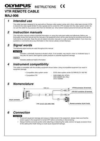
Nomenclature VTR IN connector (S terminal)
1600 mm I
VTR OUT connector (S terminal)
O R
62-pin connector VTR remote cable (MAJ-906)
6
Remote connector (9 pin D-sub)
Connection S S
To prevent equipment damage and erasure of data stored in the equipment, always make sure that the power supply to the equipment is turned OFF before connecting or disconnecting. Always hold the connector portion when attaching or detaching the cable, and do not apply excessive force to the cable portion itself. Doing so could cause equipment damage.
1. Turn the video system center and VTR OFF. 2. Plug the 62-pin connector of the VTR remote cable securely into the VTR REMOTE terminal on the rear panel of the video system center. Tighten the screws to secure the connection.
3. Plug the remote connector (marked [R]) of the VTR remote cable securely into the RS-232C terminal on the VTR rear panel as shown below. Tighten the screws to secure the connection.
4. Connect the VTR IN connector (marked [I]) of the VTR remote cable securely to the S-VIDEO INPUT terminal on the VTR rear panel. Then connect the VTR OUT connector (marked [O]) of the VTR remote cable securely to the S-VIDEO OUTPUT terminal on the VTR rear panel as shown below. S-VIDEO INPUT terminal
Video system center
RS-232C terminal
S-VIDEO OUTPUT terminal 62 pin connector VTR VTR remote cable
Remote connector VTR connectors DSR-20MD (P) S-VIDEO INPUT terminal
S-VIDEO OUTPUT terminal
RS-232C terminal
DVO-1000MD
7
Operation and storage 1. Turn the video system center ON. 2. Turn the VTR ON. 3. Set the VTR remote control mode of the video system center to [RS232C]. For details see the instruction manual of the video system center.
4. Set the VTR as shown below. For details see the VTR instruction manual. S Baud rate
:
9600bps
S REMOTE/LOCAL switch
:
REMOTE
When setting the VTR as described in Step 4. control via the VTR front panel is not possible. VTR operation can now be controlled by the remote control switches of the keyboard connected to the video system center, or by the switch on the videoscope head, as required by the procedure. However, the functions of the videoscope switch are limited to starting and pausing of the VTR recording. For setting of videoscope switches, refer to the instruction manual for the video system center. For more details on the operation of the video system center, refer to its instruction manual. If the VTR remote cable is disconnected from the video system center and the VTR, store it at room temperature in a clean, dry, well ventilated environment after removing dust and dirt. Manufactured by
Distributed by
2951 Ishikawa-cho, Hachioji-shi, Tokyo 192-8507, Japan Fax: (0426)46-2429 Telephone: (0426)42-2111
Two Corporate Center Drive, PO Box 9058 Melville, N.Y. 11747-9058, U.S.A. Fax: (631)844-5442 Telephone: (631)844-5000
6100 Blue Lagoon Drive, Suite 390 Miami, FL 33126-2087, U.S.A. Fax: (305)261-4421 Telephone: (305)266-2332
(Premises/Goods delivery) Wendenstrasse 14-18, 20097 Hamburg, Germany (Letters) Postfach 10 49 08, 20034 Hamburg, Germany Telephone: (040)237730
KeyMed House, Stock Road, Southend-on-Sea, Essex SS2 5QH, United Kingdom Fax: (01702)465677 Telephone: (01702)616333
117071, Moscow, Malaya Kaluzhskaya 19, bld. 1, fl.2, Russia Fax: (095)958-2277 Telephone: (095)958-2245
8F, Hyundai Marines Bldg., 646-1, Yeoksam-Dong, Kangnam-Gu, Seoul 135-080 Korea Fax: (02)6255-3499 Telephone: (02)1544-3200
Room 1406, E Tower, GongYuan No.6 Royal Palace, No.6 GongYuanXiJie, Jian Guo Men Nei, DongCheng District, Beijing, 100005, China Fax: (10)6518-0865 Telephone: (10)6518-8080
491B, River Valley Road #12-01/04, Valley Point Office Tower, Singapore 248373 Fax: 6834-2438 Telephone: 6834-0010
31 Gilby Road, Mount Waverley, VIC., 3149, Australia Fax: (03)9543-1350 Telephone: (03)9265-5400
GC7335 07
One Corporate Drive, Orangeburg, N.Y. 10962, U.S.A. Fax: (845)398-9444 Telephone: (845)398-9400
©2000 OLYMPUS MEDICAL SYSTEMS CORP. All rights reserved. Printed in Japan 20050415 :0000