OLYMPUS
OLYMPUS Mobile Workstations, Trolleys and Support Arms
MD-808 and MAJ-683 Support Arm Instructions Aug 2006
Instructions
2 Pages

Preview
Page 1
INSTRUCTIONS
USA: CAUTION:
Mounting supporting arm MD-808
Federal law restricts this device to sale by or on the order of a physician.
1. Place the supporting arm on the supporting arm shaft of the trolley, and securely tighten the knob. 2. Attach the probe driving unit to the joint of the supporting arm according to the instructions in the probe driving unit’s instruction manual.
SUPPORTING ARM
Mounting supporting arm MAJ-683
MD-808/MAJ-683
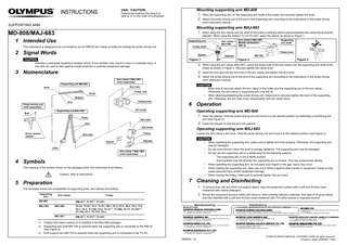
1. When using the arm clamp over the shelf of the trolley so that the shelf is placed between the clamp frame and the adjuster. When using the trolleys TC-V1/TC-US1, place the spacer as shown in Figure 1.
1 Intended Use
Supporting arm
This instrument is designed to be connected to an OLYMPUS arm clamp or trolley for holding the probe driving unit.
Arm clamp 1 MAJ-684
Arm clamp 2 MAJ-851 Mobile workstation WM-30
Adjuster
MH-709
Trolley shelf
2 Signal Words
Clamp knob Spacer
Figure 1 Indicates a potentially hazardous situation which, if not avoided, may result in minor or moderate injury. It may also be used to alert against unsafe practices or potential equipment damage.
trolley as shown in Figure 2. Securely tighten the clamp knob.
Arm clamp 2 MAJ-851 (sold separately)
Supporting arm MD-808
unit’s instruction manual.
Arm hole
•
Trolley hole
Knob
•
Stopper Clamp knob
Arm
Probe driving unit (sold separately)
Operating supporting arm MD-808 1. Open the stopper. Hold the probe driving unit and move it to the desired position by extending or shortening the
Knob
arm (see Figure 3).
Arm hole
2. Close the stopper to lock the arm into position.
Arm Arm knob Driver section adapter
Make sure to securely attach the arm clamp to the trolley and the supporting arm to the arm clamp. Otherwise, the arm clamp or supporting arm may fall off. When attaching/detaching the probe driving unit, make sure to securely tighten the knob of the supporting arm. Otherwise, the arm may move unexpectedly and can cause injury.
6 Operation
Arm knob
Supporting arm MAJ-683
Operating supporting arm MAJ-683
Frame
Arm axis
Loosen the arm clamp’s arm knob. Hold the probe driving unit and move it to the desired position (see Figure 3).
Adjuster
Spacer
•
Joint
• •
Arm clamp 1 MAJ-684 (sold separately)
4 Symbols
• •
The meaning of the symbol shown on the package and/or this instrument is as follows: Caution, refer to instructions.
•
When operating the supporting arm, make sure to tighten the knob properly. Otherwise, the supporting arm may be damaged. Do not move the arm when the knob is strongly tightened. The supporting arm may be damaged. Do not use the supporting arm in a sterile area for the following reasons: − The supporting arm is not a sterile product. − Dust particles may fall off when the supporting arm is moved. This may compromise sterility. When operating the supporting arm, do not place your fingers in the gap. Injury may occur. When rotating the supporting arm, take care not to strike it against other people or equipment. Doing so may cause personal injury and/or equipment damage. When moving the trolley, make sure to securely tighten the arm knob.
7 Cleaning and Disinfecting
5 Preparation
1. To remove dust, dirt and other non-patient debris, wipe the equipment surface with a soft and lint-free close
The list below shows the compatibility of supporting arms, arm clamps and trolleys. Supporting Arm
Arm Clamp
2. Should the equipment become soiled with blood or other potential infection materials, first wipe of all gross debris and then disinfect with a soft and lint-free close moistened with 70% ethyl alcohol or isopropyl alcohol.
∗2, TC-P2∗3, TC-US1
–
WM-30
MAJ-683
MAJ-684
TC-U1, TC-E1, TC-1, TC-P1, TB-1, TC-2, TV-2, TB-2, TS-1, TI-2, TU-1, TE-2, TI-1300, TU-2, TC-V1∗1, TI-1900, TC-T1, TC-US1∗1, TC-TR2, KT-1, TC-TF2, TK-2
MAJ-851
moistened with neutral detergent.
Trolley
MD-808
∗3
Figure 3
3. Insert the arm axis into the arm hole of the arm clamp and tighten the arm knob. 4. Attach the probe driving unit to the joint of the supporting arm according to the instructions in the probe driving
Joint
∗1 ∗2
Figure 2
2. When using the arm clamp (MAJ-851), place the trolley hole of the arm clamp over the supporting arm shaft of the
3 Nomenclature
Bolt
Supporting arm shaft
WM-30∗2, TC-P2∗3, TC-US1
Trolleys that need a spacer (it is installed in the MAJ-684 package). Supporting arm shaft MH-709 is required when the supporting arm is connected to the WM-30 (see Figure 2). EUS support arm MH-735 is required when the supporting arm is connected to the TC-P2.
Manufactured by
Distributed by
MANUFACTURER
AUTHORIZED REPRESENTATIVE IN THE EUROPEAN COMMUNITY
2951 Ishikawa-cho, Hachioji-shi, Tokyo 192-8507, Japan Fax: (042)646-2429 Telephone: (042)642-2111
(Premises/Goods delivery) Wendenstrasse 14-18, 20097 Hamburg, Germany (Letters) Postfach 10 49 08, 20034 Hamburg, Germany Fax: (040)23773-4656 Telephone: (040)23773-0
3500 Corporate Parkway, P.O. Box 610, Center Valley, PA 18034-0610, U.S.A. Fax: (484)896-7128 Telephone: (484)896-5000
5301 Blue Lagoon Drive, Suite 290 Miami, FL 33126-2097, U.S.A. Fax: (305)261-4421 Telephone: (305)266-2332
117071, Moscow, Malaya Kaluzhskaya 19, bld. 1, fl.2, Russia Fax: (095)958-2277 Telephone: (095)958-2245
Olympus-Tower, 114-9 Samseong-Dong, Gangnam-Gu, Seoul 135-090 Korea Fax: (02)6255-3494 Telephone: (02)6255-3210
A8F, Ping An International Financial Center, No. 1-3, Xinyuan South Road, Chaoyang District, Beijing, 100027 P.R.C. Fax: (86)10-5976-1299 Telephone: (86)10-5819-9000
491B, River Valley Road #12-01/04, Valley Point Office Tower, Singapore 248373 Fax: 6834-2438 Telephone: 6834-0010
KeyMed House, Stock Road, Southend-on-Sea, Essex SS2 5QH, United Kingdom Fax: (01702)465677 Telephone: (01702)616333
31 Gilby Road, Mount Waverley, VIC., 3149, Australia Fax: (03)9543-1350 Telephone: (03)9265-5400
GR5004 14
©1999 OLYMPUS MEDICAL SYSTEMS CORP. All rights reserved. Printed in Japan 20060801 *0000