Instructions for Use
52 Pages
Preview
Page 1
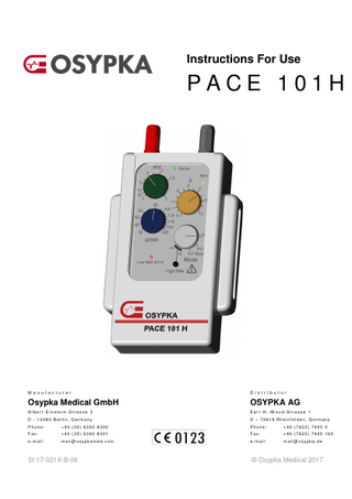
Instructions For Use
PACE 101H
M anuf ac t ur er
Di st ri but or
Osypka Medical GmbH
OSYPKA AG
Al bert- Einst ein-St rasse 3
E arl- H. -W ood-Str asse 1
D - 12489 Berli n, G erm any
D – 79618 Rhei nf el den, G ermany
Phone:
+49 (30) 6392 8300
Phone:
+49 (7623) 7405 0
F ax:
+49 (30) 6392 8301
F ax:
+49 (7623) 7405 160
e-m ail :
m ail@ osypkamed. com
e-m ail :
m ail@ osypka. de
5I-17-021X-B-06
© Osypka Medical 2017
Pace 101H – Instructions For Use
Table of Contents 1
Preface
5
1.1
General
5
1.2
Checking the Package
5
1.3
Writing Conventions of this Manual
6
2
Product Description
7
3
Indication
8
4
Contraindication
8
5
Possible Complications
9
6
Precautionary Measures and Warnings
11
7
Patient Safety
13
8
Electromagnetic Compatibility
14
9
Use and Application of PACE 101H
15
9.1
Design
9.2
Connecting Temporary Stimulation Leads
19
9.2.1
Lead Types
21
9.3
Powering On PACE 101H
22
9.4
Powering Off PACE 101H
22
9.5
Determining the Sensing Threshold
23
9.6
Determining the Capture Threshold
24
9.7
Modes of Operation
25
9.7.1 9.7.2 9.7.3
Demand Stimulation (VVI, AAI) Asynchronous Stimulation (V00, A00) High-Rate Stimulation (x2, x4)
26 27 27
9.8
Basic Rate, Stimulation Amplitude and Sensitivity Threshold
28
9.9
Battery Surveillance
29
9.10
Device Surveillance
29
5I-17-021X-B-06
15
3 / 52
Pace 101H – Instructions For Use
9.11
Environmental and Medical Therapy Hazards
30
10
Storage
31
11
Care and Maintenance
32
11.1
Care and Cleaning
32
11.2
Changing the Battery
34
11.3
Safety Check-Ups of the Pacemaker
35
11.4
Product Return Policy
36
12
Customer Service
36
13
Technical Data
37
14
Delivery Unit
41
15
Conformity According to IEC 60601-1-2
43
16
Conditions of Guarantee and Liability Restrictions
49
17
Accessories
50
4 / 52
5I-17-021X-B-06
Pace 101H – Instructions For Use
1 Preface 1.1 General Read these instructions carefully before using the product described within. Should you have any questions about these instructions or the use of this product, please contact the customer service department before using the product: In Germany:
Phone: Fax: e-mail:
+49 (7623) 7405 0 +49 (7623) 7405 - 213 mail@osypka.de
The product may only be placed in service when its proper use can be assured. According to U.S. Standards, PACE 101H is a Class III device (21 CFR 862-892 [807.87(c)]). According to European Standards, PACE 101H is a Class IIb medical product (Council Directive 93/42/EEC of 14 June 1993 (‘Medical Device Directive’), Annex IX).
1.2 Checking the Package Unpack the product and carefully check to see if any damage has occurred during shipment. Check to see if everything was delivered as listed on the shipping list. Please inform us immediately if something is missing or damaged. Claims that are filed afterwards will not be considered.
5I-17-021X-B-06
5 / 52
Pace 101H – Instructions For Use
1.3 Writing Conventions of this Manual The following conventions are used to identify special information in this manual: Note
Helpful hints and notes on the usage of the device and for understanding the modes of operation
Caution
Conditions that may damage the pacemaker or that may prevent its safe and effective use
Warning
Important facts and warnings to be observed
6 / 52
5I-17-021X-B-06
Pace 101H – Instructions For Use
2 Product Description PACE 101H is a battery-powered, external single-chamber pacemaker for clinical use. PACE 101H is connected to temporary stimulation leads (including myocardial heart wires). The connection is made directly or via a separate extension cable and adapter, if necessary. The following stimulation modes available: VVI (or AAI), V00 (or A00) as well as a highrate function. Adjustable are stimulation mode, basic rate, sensitivity threshold, pulse amplitude and high-rate (up to 720 ppm upon pressing a button). Sensed events are indicated by a green LED (Sense), stimulated pulses by a yellow LED (Stim.). As an option these events are indicated acoustically, too (stimulation mode VVI Beep). A red LED informs about the remaining battery life (Low Batt./Error). A defect of the device (failed self-test after the device was switched on) is indicated by continuously lit LEDs and an intermittent acoustic signal. If the self-test does identify any errors, the acoustic and visual signals will turn off after a few seconds. The safety features of PACE 101H include: •
Visual display of sensed and stimulated events;
•
Microprocessor-controlled pacing parameters;
•
Timely visual and acoustic warning when the battery is almost depleted;
•
Limitation of stimulation rate to 200 ppm in case of an device malfunction (runaway protection);
•
A retractable, transparent cover of the controls to prevent accidental changes of the programmed parameters.
Temporary catheters, heart wires and leads with pins having a diameter within 0.9 mm 2 mm can be connected directly to PACE 101H. Additional extension cables and adapters are available, too. This system offers a secure connection of transvenous catheters and myocardial leads, which are applied either unipolar or bipolar. Refer to applicable sections of this manual for more detailed information on the use and maintenance of PACE 101H. The technical data is summarized at the end of this manual.
5I-17-021X-B-06
7 / 52
Pace 101H – Instructions For Use
3 Indication In conjunction with a stimulation lead system, PACE 101H can be used whenever temporary atrial or ventricular stimulation is indicated. PACE 101H can be employed for therapeutic as well as diagnostic purposes or be used prophylactically. Some specific indications for temporary stimulation are: •
Complete (third-degree) or intermittent heart block
•
Symptomatic sinus bradycardia
•
Atrial or ventricular ectopic arrhythmia
•
Sick sinus syndrome (SSS)
•
Atrial tachyarrhythmia
•
Acute myocardial infarction induced heart block
•
Stimulation during a ventricular asystole
•
Usage during the replacement of an implantable pacemaker
•
Stimulation and monitoring before the implantation of a cardiac pacemaker
•
Stimulation and monitoring following heart surgery
4 Contraindication There are no contraindications with regards to the use of PACE 101H for temporary cardiac stimulation for therapy and prevention of arrhythmia. The state of health of the patient, however, can restrict the choice of operational mode and stimulation parameters. For example, a mode of operation with atrial sensing is not suitable or appropriate when atrial fibrillation occurs. This is due to the excessive and chaotic frequency of detected fibrillation waves. Overdrive-stimulation therapy must only be used in the atrium. Overdrive-stimulation in the ventricle could cause life threatening ventricular fibrillation.
8 / 52
5I-17-021X-B-06
Pace 101H – Instructions For Use
5 Possible Complications When using an external pacemaker such as PACE 101H, the following complications can arise and may lead to adverse events:
Complication
Result / Adverse Event
Infection
Sepsis
Thrombosis and pulmonary embolism
Death
Perforation of the heart
Hemopericardium, Hemothorax, Cardiac tamponade
Muscle and nerve stimulation
Patient discomfort
Dislocation of lead
System malfunction. Failure to stimulate.
Disconnection or breakage of lead contact problems at connection sites. Insufficient tightening of the collets.
Intermittent or complete failure of effective stimulation and/or sensing
Significant rise in the stimulation threshold
Loss of effectiveness of the stimulation (Exit Block)
Significant drop of the ECGsignal amplitude after lead dislocation or ingrown lead
Loss of sensing (Entrance Block)
Abnormal pacemaker settings
Erratic rhythm. Compromise in stroke volume / cardiac output
5I-17-021X-B-06
9 / 52
Pace 101H – Instructions For Use
Complication
Result / Adverse Event
Inappropriately high sensitivity setting. Sensing of R or T waves in the atrium or P waves in the ventricle. Detection of interference (noise, electromagnetic interference).
Ventricular tachycardia, ventricular fibrillation, and death, if not recognized immediately.
Overdrive stimulation in the atrium = rapid atrial pacing
Accidental conduction into the ventricle can create ventricular arrhythmia
Battery failure or exhaustion
Failure of impulse emission. Failure to stimulate.
Technical defect in the PACE 101H (failure of components)
Failure or change in the impulse emission, changed (or no) sensing, incorrect displays. Failure to stimulate.
Undetected programming errors
Chaotic rhythm
Erroneous lead connection
Device does not function properly. Chaotic rhythm. Failure to stimulate as intended.
Influence of defibrillation and RF surgery
See 9.11 Environmental and Medical Therapy Hazards for the effects of using at the same time PACE 101H and defibrillators or electro-surgical instruments.
Table 1: Possible Complications
10 / 52
5I-17-021X-B-06
Pace 101H – Instructions For Use
6 Precautionary Measures and Warnings The following list presents important precautionary measures and warnings. Additional important precautionary measures and warnings will be found in the following chapters. 1.
In order to prevent unnecessary complications, PACE 101H should only be applied and used by medical personnel with extensive experience in cardiac stimulation therapy. Additionally, the person using the device should be thoroughly familiar with the contents of this instruction manual.
2.
All lead systems are to be connected to type CF devices only because of the danger of the current being diverted to the heart. Devices that are connected to a main power supply pose increased danger due to the current diversions to the heart.
3.
Make sure that all devices in the vicinity of the patient are properly grounded.
4.
Stimulation leads provide a direct, low-resistance current path to the heart. Therefore, it is absolutely necessary that the connector plug is not touched with bare hands or come in contact with electrically conductive or wet surfaces. All possible static electricity sources must be kept away from the stimulation system.
5.
While the lead is being inserted and connected to the pacemaker, continuous ECG monitoring is mandatory. For emergency situations, a defibrillator should always be available in a ready-to-use state.
6.
ECG monitoring should be continued during all times PACE 101H is in use to signal possible complications of different reasons immediately to the medical staff.
7.
In either case it is necessary to monitor the patient and to be prepared for a failure of the pacemaker function. A back-up device for the pacemaker must be available.
8.
Error messages and conflict warnings of PACE 101H do not replace an ECG monitoring.
9.
During atrial overdrive-stimulation an accidental conduction into the ventricle is possible and may cause ventricular tachycardia. Therefore, continuous ECGmonitoring is mandatory. A defibrillator should always be available in a ready-touse state.
10.
If PACE 101H operates in an asynchronous mode, the pacing pulses may occur during the vulnerable phase of the patient’s intrinsic activity (corresponds approximately in the ECG to the T-wave); and may cause ventricular fibrillation and ventricular flutter.
5I-17-021X-B-06
11 / 52
Pace 101H – Instructions For Use
11.
When PACE 101H is used in conjunction with electro-surgical instruments or defibrillators, it is mandatory to continuously monitor the patient and to be prepared for a possible failure or malfunctioning of the pacemaker
12.
To protect the patient and the pacemaker from current passing through the pacemaker/lead-circuitry caused by defibrillation discharges, the stimulation circuit should always be opened during defibrillation if possible. Current flows caused by defibrillator discharges can endanger the patient and the high current amplitudes can also damage the pacemaker.
13.
If PACE 101H is to be used for a long period of time on a patient, then the stimulation threshold should be checked from time to time. Initially, it should be checked after a few hours, then daily because an increase of the threshold may occur.
14.
An unnecessarily high sensitivity (small sensitivity value) increases the probability that proper pacemaker functioning will be affected by external interference. If there are strong electromagnetic fields caused by telecommunication devices (like mobile phones) or other sources, an asynchronous mode should be set with a higher than the patient’s intrinsic rate.
15.
In case that PACE 101H is not used for long periods of time, the battery must be removed in order to prevent damage from possible battery acid leakage. (Such damage will not be compensated under the guarantee).
16.
The pacemaker must not be submerged in either water or any other cleaning solution. Do not use any scrubbing powder/liquid on the device.
17.
The device must not be sterilized in an autoclave. Sterilization with plasma, ultrasound, ethylene oxide or gamma radiation is also not allowed. PACE 101H can be damaged by such procedures.
18.
Connector cables, which are intended for single use, cannot be re-sterilized and reused.
19.
Only the manufacturer, or facilities authorized by the manufacturer, can perform repairs or calibration of PACE 101H.
20.
All battery powered devices can lose their function due to normal discharge of the battery. It must also be considered that the pacemaker can stop operating as a result of an unpredictable component failure. The patient should not be left unattended by the medical staff and should always be supervised by a monitoring system.
21.
Use only 9 V primary batteries for PACE 101H. Re-chargeable batteries (accumulators) should not be used (possibly low capacity and unstable charge condition may cause a malfunction of the pacemaker).
12 / 52
5I-17-021X-B-06
Pace 101H – Instructions For Use
22.
When used as intended, PACE 101H does not contain any parts which are subject to wear and tear.
7 Patient Safety The external pulse generator PACE 101H meets all applicable international standards for patient safety: IEC 60601-1
Medical electrical equipment. General requirements for safety
IEC 60601-1-2
Medical electrical equipment. Electromagnetic compatibility
IEC 60601-2-31
Medical electrical equipment. External cardiac pacemakers
In the event that the patient is connected to multiple electrical devices, the sum of leakage currents may exceed the allowable limits.
5I-17-021X-B-06
13 / 52
Pace 101H – Instructions For Use
8 Electromagnetic Compatibility The external pulse generator PACE 101H meets all applicable international standards with respect to electromagnetic compatibility (EMC). IEC 60601-1-2
Medical electrical equipment. Electromagnetic compatibility
CISPR 11
Industrial, scientific and medical radio-frequency equipment. Electromagnetic disturbances
IEC 61000
Electromagnetic compatibility
Some sources of radiated emissions may impact the proper function of PACE 101H: •
Electrosurgical instruments operating with radio frequency
•
Devices for diathermy therapy
•
Magnetic resonance imaging (MRI)
• Medical telemetry systems Special electromagnetic compatibility (EMC) precautions should be taken when using electrical medical equipment such as PACE 101H: A
Portable and mobile RF communications equipment, such as mobile phones, can affect the function of PACE 101H. Mobile phones with a rated maximum output power of 2 Watt and a transmitter frequency up to 2.5 GHz should be used no closer to any part of PACE 101H (including patient cables and sensors) than a recommended separation distance of 10 m (30 ft).
B
Floors should be wood, concrete or ceramic tile. If floors are covered with synthetic materials, the relative humidity should be at least 30 %.
C
Power frequency magnetic fields should be at levels characteristic of typical commercial or hospital environments.
For further information and guidance regarding EMC, refer to chapter 15 Conformity According to IEC 60601-1-2 on page 43.
14 / 52
5I-17-021X-B-06
Pace 101H – Instructions For Use
9 Use and Application of PACE 101H 9.1 Design PACE 101H with its controls and terminals is shown in Figure 1 and Figure 2.
Figure 1: External Pulse Generator PACE 101H Front Face
5I-17-021X-B-06
15 / 52
Pace 101H – Instructions For Use
Figure 2: External Pulse Generator PACE 101H Rear View
16 / 52
5I-17-021X-B-06
Pace 101H – Instructions For Use
1
Lead connection sockets: Protected safety connectors for plugs with a diameter of 0.9 mm to max. 2.0 mm. Different pole
(–) :
black
Indifferent pole
(+) :
red
2
Green LED blinks synchronous to the sensed P-/R-wave.
3
Yellow LED blinks synchronously with the stimulation pulse.
4
Control for setting the stimulation pulse amplitude.
5
Mode Switch: Off
Device is turned off
VVI
Inhibited pacemaker operation
VVI Beep
Inhibited pacemaker operation with acoustic signal during sensing and stimulation (two different tones)
x2
Stimulation rate times two (High-Rate stimulation) enabled
x4
Stimulation rate times four (High-Rate stimulation) enabled
During High-Rate stimulation an acoustic signal is given automatically. 6
Button to activate High-Rate stimulation (Basic Mode: V00 Beep)
7
Control for setting the sensing threshold for the P-/R-wave. In position ‘f’ the pacemaker stimulates in the asynchronous (fixed rate) mode.
8
Control for setting the basic stimulation rate (‘basic rate’, or just ‘rate’) .
9
Red LED indicates errors and low battery voltage.
10
Plexiglas cover. Protects against accidental change of the chosen parameters.
11
Ridge for attaching an arm strap.
12
Battery compartment (see Figure 2)
5I-17-021X-B-06
17 / 52
Pace 101H – Instructions For Use
Figure 3: External Pulse Generator PACE 101H Top View The internationally recognized pictograms have the following meaning:
Classification: CF (cardiac floating) applied part, defibrillation protected Symbol: Follow instruction for use. Symbol: Follow instruction for use. PACE 101H is marked with the symbol of a crossed-out garbage. The symbol indicates that the European WEEE1 guideline applies to the disposal method of the device. Symbol for Conformité Européenne (device and manufacturer meet all requirements of European guideline 93/42/EWG) Symbol: Caution
PACE 101H can be used as either a demand- (P-/R-wave inhibited) or an asynchronous pacemaker. In the demand mode, the inhibition of the stimulation is caused by intrinsic activity. No impulse is given if the PP/RR interval is shorter than the interval of the chosen stimulation rate. The pacemaker only stimulates if the interval of the pacemaker is exceeded. In these cases, the stimulation proceeds at a constant rate until the pacemaker is inhibited by a spontaneous action (such as a premature atrial complex (PAC) 1 European Guideline 2002/96/EG on Waste Electrical and Electronic Equipment (WEEE)
18 / 52
5I-17-021X-B-06
Pace 101H – Instructions For Use
or a premature ventricular complex (PVC)) or a faster intrinsic rhythm. To prevent inappropriate sensing after a paced or sensed event, PACE 101H has a refractory period of 250 ms. The Mode switch allows the user to select between standard VVI stimulation with (‘VVI Beep’) or without (‘VVI’) audible signal upon sensed events and stimulation pulses, and High-Rate stimulation (‘x2’, ‘x4’). In the modes “VVI” or “VVI Beep” the pacemaker recognizes, depending on the set sensitivity value, intrinsic activity of the heart and stimulates or inhibits accordingly. In order to use the demand function of PACE 101H, the sensing threshold must be set to a value significantly lower than the R-wave peak amplitude (for instance, 2 mV). Alternatively, PACE 101H is operated in asynchronous mode (V00) by turning the sensing threshold knob completely counter-clockwise to the left (position indicated by ‘f’), causing the pacemaker to stimulate at a fixed frequency without inhibition. PACE 101H can be used for pacing therapy in the ventricle or in the atrium. It is also possible to stimulate in High Rate mode. Depending on the setting of the Mode switch to ‘×2’ or ‘×4’, the stimulation rate will be doubled or quadrupled when the “High Rate” button is pushed. PACE 101H stimulates at a fixed rate, independent of the set sensitivity value. After the ‘High Rate’ button is released, the pacemaker reverts to the previous mode of operation.
9.2 Connecting Temporary Stimulation Leads PACE 101H provides two terminals located on top of the device. The receptacles (Figure 3) accommodate pin connectors with a diameter of 0.9 mm to 2.0 mm and, thus, most common connectors of pacing leads or electrodes or pacing (heart) wires. The indifferent pole (+ pole) is colored red. The different pole (- pole) is black. To connect the stimulation leads to PACE 101H, proceed as follows: 1.
PACE 101H must be turned off before any lead is connected. Make sure the Mode Switch [5] is in the ‘Off’ position (Figure 1).
2.
Loosen the collets of the terminals by rotating the screws counter-clockwise.
3.
w/ Use of an Extension Cable
w/o Use of an Extension Cable
Connect the extension cable to the pacemaker b e f o r e connecting the stimulation leads to the extension cable.
5I-17-021X-B-06
19 / 52
Pace 101H – Instructions For Use
Connect the stimulation lead to the extension cable. 4.
Connect the stimulation lead to the pacemaker.
Ensure correct polarity: Bipolar Leads
Unipolar Leads
Transvenous
Pacing (Heart) Wires
Connect the lead’s distal pole to the black terminal (-) and its proximal pole to the red terminal (+)
Polarity is not relevant
Connect lead to the black terminal (-) and a large-surface indifferent electrode to the red terminal (+)
5.
Secure the connections by tightening the connector screws by hand.
6.
Turn the pacemaker on and select the desired mode of operation.
7.
Determine the cardiac capture and sensing thresholds.
8.
Monitor safe and effective function of the pacemaker using an ECG monitor.
Warning
During lead connection, powering on, and setup of the pacemaker, the patient’s ECG must be monitored. Make sure a defibrillator is on hand and ready-to-use for emergencies such as development of ventricular tachycardia.
Warning
Stimulation leads provide a low-resistance electrical path directly to the heart. Make sure that any part of the electrically conductive part of the lead or lead extension is not touched with bare hands nor has contact with other electrically conductive or wet surfaces. Keep all possible sources of static electricity away from the stimulation system including the pacemaker, leads and extensions. Before handling the pacemaker, the patient cable, or the indwelling stimulation lead, the electrostatic potential between user and patient must be equalized.
20 / 52
5I-17-021X-B-06
Pace 101H – Instructions For Use
9.2.1 Lead Types For temporary stimulation of the heart with PACE 101H, temporary transvenous leads or permanent leads, regardless of whether they are of bipolar or unipolar configuration, can be used. The use of myocardial leads is also permissible. Temporary, transvenous pacing leads: These leads are advanced into the heart via a vein and are connected to PACE 101H either directly or by means of an extension cable. Heart wires (myocardial pacing leads) Heart wires (myocardial leads) are affixed to the heart during open heart surgery, when it is expected that the patient may need stimulation for a limited period of time after surgery. Usually heart wires are connected to PACE 101H by means of an extension cable. Permanent pacing leads: Prior to implantation of a permanent pacemaker, or during a pacemaker change, stimulation may be properly maintained with the assistance of PACE 101H. The permanent lead is connected to PACE 101H either directly or by means of an extension cable.
Warning
All lead systems are to be connected to type CF devices only because of the danger of the current being diverted to the heart. Devices that are connected to a main power supply pose increased danger due to the current diversions to the heart.
For exact specifications of leads and patient cables, please refer to our product catalog.
5I-17-021X-B-06
21 / 52