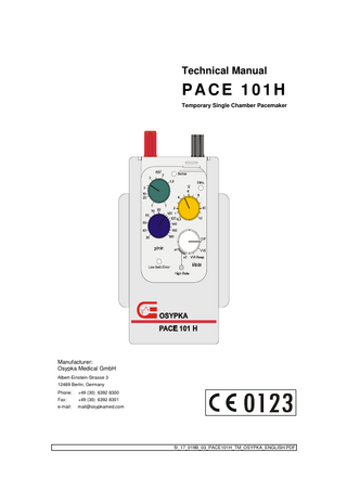
Technical Manual
27 Pages
Preview
Page 1
Technical Manual
PACE 101H Temporary Single Chamber Pacemaker
Manufacturer: Osypka Medical GmbH Albert-Einstein-Strasse 3 12489 Berlin, Germany Phone: Fax:
+49 (30) 6392 8300 +49 (30) 6392 8301
e-mail:
mail@osypkamed.com
5I_17_019B_03_PACE101H_TM_OSYPKA_ENGLISH.PDF
Table of Contents 1
FUNCTION CHECK ... 3
1.1 MECHANICAL INSPECTION ... 3 1.2 ELECTRICAL MEASUREMENT AND INSPECTION ... 3 1.2.1 Using a Pacemaker Test Equipment ... 3 1.2.2 Using an Oscilloscope and a Signal Generator ... 4 2
SAFETY CHECK ... 6
2.1 MICRO/MACRO SHOCK PROTECTION TESTS ... 7 2.1.1 Measurement of Patient Leakage Current ... 8 2.1.2 Insulation Test... 9 2.2 MEASUREMENT OF PATIENT AUXILIARY CURRENT ... 9 3
PULSE GENERATOR TIMING ... 10
3.1 3.2 3.3 3.4 3.5 3.6
TIMING CYCLE W ITHOUT INTRINSIC RHYTHM ... 10 TIMING CYCLE WITH DETECTED R-W AVE ... 11 TIMING CYCLE WITH R-W AVE IN AUTOSHORT OR BLANKING ... 12 TIMING CYCLE WITH R-WAVE IN NOISE TIME ... 13 TIMING CYCLE WITH R-WAVE IN REFRACTORY TIME ... 14 TIMING CYCLE WITH R-WAVE AFTER REFRACTORY TIME ... 15
4
APPENDICES ... 16
4.1 STIMULATION AMPLITUDE ACCORDING TO ISO DEFINITION... 16 4.2 W AVEFORM OF STIMULATION PULSE ... 17 4.3 SENSITIVITY FOR SIN² TEST IMPULSES... 18 4.4 LIST OF MAIN COMPONENTS ... 19 4.5 ELECTRICAL CIRCUITRY AND ASSEMBLY DRAWINGS ... 19 TM 4.6 FUNCTION AND SAFETY CHECK WITH SIGMAPACE 1000 ... 22 4.6.1 Visual Inspection ... 22 4.6.2 Test Equipment & Test Set Up ... 22 4.6.3 Supply Current & Power Management ... 22 4.6.4 Patient Auxiliary Current ... 23 4.6.5 Pulse Amplitude ... 24 4.6.6 Pulse Duration ... 24 4.6.7 Rate ... 24 4.6.8 Sensitivity ... 24 4.6.9 Noise Detection... 25 4.6.10 Refractory Period... 25 4.6.11 Test Protocol ... 26
Document: 5I-17-19X-B-03
Page 2 of 27
1
Function Check
1.1
Mechanical Inspection
The following inspection must be carried out: •
Inspect the device, connections and accessories for visible damage.
•
Open each receptacle and insert 2 mm pin. Tighten both receptacles and check for fast hold by pulling on each pin.
•
Open front window panel and check integrity of all dial knobs. Knobs should be tight. Close front panel window.
•
Check battery compartment for easy opening and closing. Verify that the 9V battery is in place.
•
Check seal on housing screws.
1.2
Electrical Measurement and Inspection
1.2.1 Using a Pacemaker Test Equipment The electrical part of the function check shall be made with special pacemaker test equipment. There are different models available on market. The chosen model's instructions for use must be followed. The following measurements and inspections must be carried out: • • • • •
Measuring the pulse amplitude Measuring the pulse width Measuring the rate Measuring the sensitivity Inspecting the battery surveillance
Additionally the following measurements and inspections may be made: • • • •
Measuring the battery surveillance Measuring the refractory period Measuring the high rate stimulation Inspecting the interference behavior
For inspecting and/or measuring the Battery surveillance the following information is given. If switched on, the pacer measures the battery voltage every second. If the voltage falls under a specified level, the red LED “Low Batt/Error“ flashes and an acoustic signal is given. The flashing interval and the acoustic signal repetition interval depend on the battery level reached. Table 1 shows the values.
Document: 5I-17-19X-B-03
Page 3 of 27
Table 1: “Low Batt/Error” LED flashing and acoustic signal repetition interval depending on battery level Voltage level
LED flashing interval Acoustic signal repetition interval #1
7.20 V ± 0.20 V 7.00 V ± 0.20V 6.80 V ± 0.20 V 6.60 V ± 0.20 V 6.40 V ± 0.20 V 6.20 V ± 0.20 V
#2
5 sec 4 sec 3 sec 2 sec 1 sec 0.2 sec
#3
5 min 4 min 3 min 2 min 1 min 0.6 sec
1.2.2 Using an Oscilloscope and a Signal Generator If no special pacemaker test equipment is a available then the pulse amplitude, pulse duration, rate and sensitivity may also be inspected by means of an oscilloscope and a signal generator. The function check shall start with the following basic inspection : • • • • • • •
Open front window panel of the unit Turn Pace 101H on "Mode" dial to "VVI". The green, red and yellow indicator will light up momentarily Turn "mV" dial to "f". Turn "V" dial to 6. Turn "p/min" (pulses per minute) dial to 60 Check that the "Stim." indicator (yellow) is flashing. Check that all other indicators ("Sense" and "Low Batt./Error") are not lit. Turn "Mode" dial to VVI Beep and check whether a beep is heard with every "Stim." indicator flash. Turn the unit off.
Assuming there is a 2-Channel Oscilloscope available, then the following table gives a short description of oscilloscope front panel knobs and their function: Knob name
Function and Select for PACE 101H
Input CH A Position Polarity Volts/cm Mode Power Intensity Focus Sweep/time Triggering Slope Coupling Source Position
A Input channel A Moves signal up and down on oscilloscope screen DC 2 A ON/OFF Signal brightness Centralizes light 0.1 ms, 1 ms, 0.2 s IN DC CH A Moves signal left and right on oscilloscope screen
Document: 5I-17-19X-B-03
Page 4 of 27
Set up of the oscilloscope by carrying out the following steps: •
Turn the oscilloscope ON.
•
Verify all knobs are in calibration position.
•
Connect oscilloscope test cable to Channel A input.
•
Connect test cable to the pin of black receptacle.
•
Connect ground wire of test cable to the pin of red receptacle.
•
Connect a 500 Ohm load resistor parallel to black and red receptacle.
•
Set polarity switch of oscilloscope to "DC".
Inspecting of pulse amplitude, pulse duration and rate shall be done as follows : •
Turn PACE 101H power ON knob to VVI position.
•
Turn "mV" dial to "f", "V" dial to 6, "p/min" (pulses per minute) dial to 60.
•
Verify “trigger” knob of oscilloscope is pushed IN. Turn the knob slowly clockwise until a display of PACE 101H output signals is on screen.
•
Set sweep dial of oscilloscope at 1 msec/cm.
•
Set sensitivity dial of oscilloscope at 2 V/cm. A signal pulse should appear on screen. The amplitude of the (negative) pulse should be displayed in 3 cm deflections.
•
Set sweep dial of oscilloscope at 0.1 msec/cm. The pulse duration of the (negative) pulse should be displayed in 7.5 cm deflections.
•
Set sweep dial of oscilloscope at 0.2 sec/cm. The distance between two pulses should be displayed in 5 cm deflections.
•
Set "Mode" dial of PACE 101H to 2X. Press High Rate button and observe the distance between pulses is two times shorter (faster).
Inspecting of sensitivity shall be done as follows : •
Find a signal generator capable for providing triangle test pulses.
•
Connect PACE 101H to the signal generator.
•
Turn PACE 101H power ON to VVI position.
•
Turn "mV" dial to "5", "V" dial to 6, "p/min" (pulses per minute) dial to 60.
•
Supply a triangle test pulse (2 ms rising edge/13 ms following edge ) of 3.0 mV amplitude and 100 p/min repetition rate to PACE 101H.
•
Turn "mV" dial slowly clockwise and observe whether the device starts with inhibition at the “3” position. If the PACE 101H switches from stimulation to inhibition then the green indicator “Sense” flashes instead of the yellow indicator “Stim.”.
Document: 5I-17-19X-B-03
Page 5 of 27
2
Safety Check
This safety check is based on the following international standards: IEC 60601-1:1988
Medical electrical equipment - Part 1: General requirements for safety
IEC 60601-1/A1:1991
Medical electrical equipment - Part 1: General requirements for safety - Amendment 1
IEC 60601-1/A2:1995
Medical electrical equipment - Part 1: General requirements for safety - Amendment 2
IEC 60601-2-31:1994
Medical electrical equipment - Part 2: Particular requirements for the safety of external cardiac pacemakers with internal power source.
IEC 60601-2-31/A1:1997
Medical electrical equipment - Part 2: Particular requirements for the safety of external cardiac pacemakers with internal power source/Amendment No. 1.
The following measurement equipment and auxiliary means are needed: •
Safety tester according to IEC 60601-1
•
Digital multimeter
•
Oscilloscope
•
High voltage tester
•
Metal foil, to get an intimate contact with the insulating enclosure of the PACE 101H
•
A metal surface of 20 cm × 25 cm
•
Div. leads with 2 mm and 4 mm plugs, measuring probes, a 100 kΩ resistance
From a safety point of view, an external pulse generator belongs to the internally powered equipment class and has a CF degree of protection against electric shock. The external pulse generator PACE 101H is characterized as follows: an enclosure made of insulating material; an applied part with the two patient connections DIFF (black terminal) and INDIFF (red terminal). The following chapters describe all safety tests contained in the above-mentioned standards, which are applicable to external pulse generators with internal power supply. As a safety check of the PACE 101H at least measuring the patient auxiliary currents must be carried out.
Document: 5I-17-19X-B-03
Page 6 of 27
2.1
Micro/Macro Shock Protection Tests
The purpose of this test is to verify the micro/macro shock protection according to the above standards which includes measurement of: •
patient leakage current between patient connections and enclosure (source IEC 60601-1, subcl. 19)
•
dielectric strength (source IEC 60601-1 subcl. 14.6 c and IEC 60601-2-31 subcl. 5.2, IEC 60601-1 subcl. 20)
The measuring methods of this test shall strongly agree with the respective IEC standards. The test is divided into two parts: Measurement of Patient Leakage Current, Insulation Test.
Table 2 shows the allowable values for the leakage currents. Table 2: Allowable values for leakage current Current
Unit
Allowable Value
#1
Patient leakage current between diff (“-“, black) connection and enclosure Patient leakage current between indiff (“+”, red) connection and enclosure Patient leakage current with voltage 250 VAC applied between diff connection and enclosure Patient leakage current with voltage 250 VAC applied between indiff connection and enclosure
#2
#3
mA
0.01
mA
0.01
mA
0.05
mA
0.05
Table 3 shows the insulation to be tested. Table 3: Insulation to be tested Insulation to be tested Case B-d (Basic Insulation) #1
Between enclosure and diff (“-“, black) patient connection Between enclosure and indiff (“+”, red) patient connection
Document: 5I-17-19X-B-03
Page 7 of 27
2.1.1 Measurement of Patient Leakage Current The test shall be carried out with the safety tester. Its instructions for use shall be exactly followed. Normal Condition
For the normal condition the standard ICE 60601-1, subcl. 19.4 h 6 shall be taken into account where figure 23 shows the proper measuring device. The exterior surface of the pacer made of insulating material shall be covered with a metal foil (according to IEC 60601-1, subcl. 19.4 g 5) of max. 10 x 20 cm, which shall be pressed against the insulating material of the enclosure (using foam/rubber of the same dimension as the metal foil). According to the standard IEC 60601-1, subcl. 19.1 e /Appendix K the patient leakage current shall be measured between each patient connection and the enclosure covered with the metal foil. The pacer shall be switched on and the following parameters shall be set: VVI, 6 V,70 ppm, 2 mV. In particular the patient leakage current shall be measured between the parts and the values shall not exceed the values given in Table 2.
Single Fault Condition
According to the standard IEC 60601-1, subcl. 19.1 e /Appendix K and the ICE 60601-1, subcl. 19.4 h 7 (measuring device see figure 24) the patient leakage current shall be measured between each patient connection and the enclosure covered with the metal foil for single fault condition applying 250 V (in accordance with IEC 60601-1, subcl. 19.1 b) to each patient connection. The enclosure made of insulating material shall be placed in any position of normal use upon a flat metal surface connected to earth with dimensions at least equal to the planprojection of the enclosure (see ICE 60601-1, subcl. 19.4 h 7). The pacer shall switched on and the following parameters shall be set: VVI, 6 V,70 ppm, 2 mV. All other constraints described in case of normal condition for measuring the patient leakage current are also valid for single fault condition. In particular the patient leakage current shall be measured for single fault condition in following cases: 1. with voltage 250 VAC between diff (“-”, black) connection and enclosure 2. with voltage 250 VAC between indiff (“+”, red) connection and enclosure The measured values shall not exceed the values given in Table 2.
Document: 5I-17-19X-B-03
Page 8 of 27
2.1.2 Insulation Test The test shall be carried out with the high voltage tester. Its instructions for use shall be exactly followed. The insulation test shall occur according to IEC 60601-1, subcl. 20.2 B-d. Values of test voltages are specified in IEC 60601-1, subcl. 20.3, table V. In case of the pacer a basic insulation shall be tested. The exterior surface of the pacer made of insulating material shall be covered with a metal foil (according to IEC 60601-1, subcl. 19.4 g 5) of max. 10 x 20 cm, which shall be pressed against the insulating material of the enclosure (using foam/rubber of the same dimension as the metal foil). Care shall be taken that the metal foil is positioned in a manner that flashover does not occur at the edges of insulation linings. If possible, the metal foil should be moved so as to test all parts of the surface. During the insulation test the pacer shall be switched off. The insulation test shall be done for a reference voltage of U ref ≤ 50 V . The test voltage shall be equal to 500 V. The test shall be carried out in accordance with IEC 60601-1, subcl. 20.4. Initially, not more than 250 V shall be applied, then the test voltage shall be gradually raised over a period of 10 s to 500 V, which shall be maintained for 1 min. after which it shall be gradually lowered over a period of 10 s to less than 250 V. The insulation test shall occur between the parts shown in Table 3.
2.2
Measurement of Patient Auxiliary Current
The purpose of this test is to verify the tissue protection, which includes measurement of the patient auxiliary current (source IEC 60601-2-31, subcl. 19.3 a) The Patient Auxiliary Current shall be measured according to the standard IEC 60601-2-31, subcl. 19.3 a. The test conditions are described in the standard IEC 60601-2-31, subcl. 19.4 j 4. For measurement of patient auxiliary current the equipment shall be connected as shown in figure 27 of the general standard to a d.c. measuring device with an input resistance of 100 kΩ . The equipment shall be connected to the measuring device for a minimum of 5 min. before making the patient auxiliary measurement. The patient auxiliary current will be measured just before the pacing pulse. In this case the measured voltage shall not exceed 100 mV . According to the IEC 60601-1, subcl. 19.1 f and g /Appendix K, the measurement of patient auxiliary current shall be done between the diff connection and the indiff connection.
Document: 5I-17-19X-B-03
Page 9 of 27
3
Pulse Generator Timing
3.1
Timing Cycle Without Intrinsic Rhythm
After the intervention interval (1/basic rate) has elapsed a stimulation pulse will be emitted. Figure 1 shows the timing.
1. intervention (pulse width 750µs)
2. intervention
I/O channel intervention time
min. 330ms
refractory time after intervention
250ms
noise time blanking time after intervention
212ms 80ms
autoshort time 35ms Figure 1: Timing cycle without intrinsic rhythm
Document: 5I-17-19X-B-03
Page 10 of 27
3.2
Timing Cycle with Detected R-Wave
The detection of a R-wave in the sensing phase inhibits the emission of the next stimulation pulse and restarts all intervals except the autoshort time. Figure 2 shows the timing.
detected R-wave
intervention
I/O channel intervention time
min. 330ms
refractory time after R-wave detection
250ms
noise time blanking time after R-wave detection
212ms 80ms
autoshort time
Figure 2: Timing cycle with detected R-wave
Document: 5I-17-19X-B-03
Page 11 of 27
3.3
Timing Cycle with R-Wave in Autoshort or Blanking
During autoshort or blanking no R-wave will be detected. Figure 3 shows the timing.
1. event
unrecognized R-wave
intervention
I/O channel intervention time
min. 330ms
refractory time after R-wave detection
250ms
noise time blanking time after R-wave detection
212ms 80ms
autoshort time 35ms Figure 3: Timing cycle with R-wave in autoshort or blanking
Document: 5I-17-19X-B-03
Page 12 of 27
3.4
Timing cycle with R-wave in noise time
If the blanking interval has elapsed the pacemaker can receive signals. But as long as the noise interval hasn’t elapsed, such received signals will be recognized as noise. As a result noise time and blanking time will be restarted. Refractory time and intervention interval will not be effected and continue running. All signals received in the restarted noise interval will be handled in the same manner. If the intervention interval elapsed, a stimulation pulse will be emitted and a new intervention interval will be started. Figure 4 shows the timing.
1. event
detected R-wave
intervention
I/O channel intervention time
min. 330ms
refractory time after R-wave detection
250ms 212ms
noise time blanking time after R-wave detection
212ms 80ms
80ms
autoshort time 35ms
Figure 4: Timing cycle with R-wave in noise time
Document: 5I-17-19X-B-03
Page 13 of 27
3.5
Timing cycle with R-wave in refractory time
A R-wave received in the refractory time will be assumed as a first noise signal. For this reason a noise time and blanking time will be restarted. Refractory time and intervention interval will not be effected and continue running. Because of the restarted blanking time the pacemaker’s ECG input is closed. Figure 5 shows the timing.
1. event
detected R-wave
intervention
I/O channel intervention time
min. 330ms
refractory time after R-wave detection
250ms
noise time blanking time after R-wave detection
212ms 80ms
80ms
autoshort time 35ms
Figure 5: Timing cycle with R-wave in refractory time
Document: 5I-17-19X-B-03
Page 14 of 27
3.6
Timing Cycle with R-wave After Refractory Time
After refractory time has elapsed a R-wave is recognized as the patient’s intrinsic signal. The running intervention interval will be stopped and no stimulation pulse will be emitted. The intervention interval, the refractory time, the noise time as well as the blanking time will be restarted. Autoshort will not be performed. The timing cycle is shown in Figure 6.
1. event
detected & valid R-wave
I/O channel
intervention
min. 330ms
intervention time refractory time after R-wave detection
250ms
250ms
noise time blanking time after R-wave detection
212ms 80ms
212ms 80ms
autoshort time 35ms
Figure 6: Timing cycle with R-wave after refractory time
Document: 5I-17-19X-B-03
Page 15 of 27
4
Appendices
4.1
Stimulation Amplitude According to ISO Definition
The amplitude of the stimulation pulse indicated on the PACE 101H scale is equal to the peak pulse amplitude. This was chosen for an easy measurement of the pulse amplitude, but it differs from the test procedure in ISO 5841-1, Sub clause B.2.2 where the pulse amplitude is calculated from the time integral over voltage divided by the pulse duration. The pulse duration shall be measured between the points on the pulse waveform where the amplitude is equal to one-third of the peak pulse amplitude. With the following equation the ISO-amplitude can be calculated from the peak pulse amplitude: −
D
1 − e RL C AISO = APEAK ( ) D RL C with D:
pulse duration (0.75 ms),
RL:
load resistance and
C:
capacitor in load circuit (3.3 µF in PACE 101H at resistive load).
Table 4 shows calculated values for standard load RL = 500 Ω . Table 4: Peak and ISO amplitudes
Document: 5I-17-19X-B-03
APEAK / V
AISO / V
1 2 3 4 5 6 7 8 10 12
0.80 1.60 2.41 3.21 4.01 4.81 5.61 6.41 8.01 9.62
Page 16 of 27
4.2
Waveform of Stimulation Pulse
Figure 7 shows the waveforms of the stimulation pulse.
Figure 7: Stimulation pulse (amplitude 9V, resistive load 500 Ohm)
Document: 5I-17-19X-B-03
Page 17 of 27
4.3
Sensitivity for sin² Test Impulses
The sensitivity S (in mV) of the PACE 101H is adjusted by the manufacturer applying the triangle 2ms/13ms test impulse as specified in ISO 5841-1, Sub clause B.1.4 (SISO). With the following equations the corresponding sensitivities for sin² test impulses can be calculated: 15 ms pulse duration:
Ssin 2 / 15 ms = 0.77 * S ISO
25 ms pulse duration:
S sin 2 / 25 ms = 0.83 * S ISO
40 ms pulse duration:
Ssin 2 / 40 ms = 1.19 * S ISO
The formulas have to be interpreted as in the following example: If the sensitivity of the PACE 101H is set to 1 mV and a 15 ms-sin² test impulse is used, it is as if the sensitivity has been set to 0.77 mV. With other words: A 15 ms-sin² impulse with an amplitude of 0.77 mV will just be recognized by the PACE 101H, when its sensitivity parameter is set to "1 mV". The formulas can also be reversed like in the following example: When a 15 ms-sin² impulse with an amplitude of 1 mV shall just trigger the PACE 101H, its sensitivity must be set to 1.3 mV (= 1/0.77 mV).
Document: 5I-17-19X-B-03
Page 18 of 27
4.4
List of Main Components
Pos.
Quantity
Drawing Number
01
1
5I-25-069Z-D-00
Knob, blue
02
1
5I-25-069Z-E-00
Knob, green
03
1
5I-25-069Z-F-00
Knob, yellow
04
1
5I-25-069Z-G-00
Knob, white
05
1
5I-27-503A-X-02
PCB, SMD assembled
06
1
5I-28-045Z-A-01
Enclosure, lower part, gray
07
1
5I-28-047Z-A-00
Battery cover, gray
08
2
5I-28-049Z-A-00
Arm cuff strap, gray
09
1
5I-28-067Z-B-01
Enclosure, upper part, gray
10
1
9E-28-8011-A-00
LED, green, 3 mm
11
1
9E-28-8012-A-00
LED, red, 3 mm
12
1
9E-28-8034-A-00
Switch, rotary
13
1
9E-28-8035-A-00
Switch, pushbutton
14
1
9E-28-8044-A-00
Potentiometer, 10K
15
1
9E-28-8045-A-00
Potentiometer, 50K
16
1
9E-28-8189-A-00
LED, yellow, 3 mm
17
1
9E-28-8215-A-00
Signal device, piezo
18
1
9E-28-8219-A-00
Diode, Zener 5V8
19
1
9E-28-8225-A-00
Quartz crystal
20
1
9E-28-8227-A-00
Potentiometer, 500K
21
1
9F-28-8000-A-00
Battery clip
22
1
9X-28-0052-A-00
Battery, Alkaline 9V
4.5
Description
Electrical Circuitry and Assembly Drawings
See following two pages
Document: 5I-17-19X-B-03
Page 19 of 27
Document: 5I-17-19X-B-03
Page 20 of 27