Instruction Manual
151 Pages
Preview
Page 1
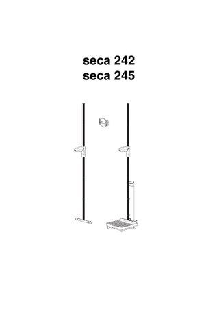
seca 242 seca 245
English
1. Congratulations! In the seca 242/seca 245 electronic measuring rod, you have acquired a highly accurate and simultaneously sturdy piece of equipment. seca has been putting its experience at the service of health for over 150 years and as market leader in many countries of the world, is always setting new standards with its innovative developments in weighing and measuring. seca 242/seca 245 measuring rods are used for diagnosis and treatment in hospitals and doctors’ surgeries. The display unit is separate from the slide unit. The value determined is transmitted by radio. Power is provided exclusively by batteries and there are no annoying cables.
The seca 242 measuring rod is fixed directly to the wall – you can define the height at which it is fixed, and thus the measuring range, yourself. The seca 245 measuring rod is supplied with a statometer. This can be moved on castors, allowing it to be used on a mobile basis. The height displayed can be switched between centimetres (cm) and inches (ins). On both models, the current value can be specified as a temporary zero point, allowing relative measurements of extremities, for example, to be made. The measuring rod is of a very sturdy construction, and will give you long and reliable service.
2. Safety Before using the new measuring rod, please take a little time to read the following safety instructions. • seca 245 only: ensure that the patient • Follow the instructions in the instruction does not lean against the measuring rod manual. risk of falling! • You must not drop the measuring rod or • Have repairs performed solely by audisplay housing nor subject them to viothorised persons. lent shocks. • After measuring height, push the slide unit back up – risk of injury!
Model 242/245
GB 15
3. Before you really start … Unpacking – Remove the packaging. The scope of supply includes: seca 242 • measuring rod, bottom part • measuring rod, top part, with head stop • heel plate • display unit • desk-top stand • wall bracket • 5 mounting screws • 5 rawlplugs • 20 spacers • 2 cylindrical bolts (plastic) and nuts • 1 bag containing a pan-head tapping screw • 10 AA 1.5 V batteries • 1 instruction manual
seca 245 • measuring rod, bottom part, premounted to column • measuring rod, top part, with head stop • statometer platform • display unit • desk-top stand • wall bracket • 2 mounting screws • 1 bag containing a pan-head tapping screw • 10 AA 1.5 V batteries • 1 instruction manual
16
Assembly seca 242 – Select a location for attaching the measuring rod where the floor is level and unyielding. In order to avoid damage to the measuring rod during use, the heel plate must be supported against the wall. The number of spacers used determines the distance of the measuring rod from the wall. You need to use at least one spacer for each of the two mounting points. – Place the spacers on top of one another and screw them to the heel plate using the plastic nuts and bolts. Alternatively – Mark drill holes for the heel plate. – Drill using a 5 mm drill bit. – Push the rawlplugs supplied into the holes. – Mount the heel plate and the spacers using two screws.
– Remove the cable tie (provided for transport purposes) on the top measuring rod. – Push the top measuring rod onto the plastic guide of the bottom measuring rod and screw it tight using the panhead tapping screw. – Place the bottom measuring rod on the heel plate and hold the measuring rod up to the desired point of attachment. Use a spirit level to align it in the perpendicular. – Mark the drill hole for the measuring rod. – Drill using a 5 mm drill bit. – Push the rawlplug into the hole. – Push the bottom measuring rod onto the heel plate. – Put the spacers between the measuring rod and the wall and fix the measuring rod in position.
Model 242/245
1.
2.
3.
GB 17
seca 245 – Put the column in the opening. – Screw the column to the platform from underneath. If necessary, place the platform carefully on its side to tighten up the screws. – Then stand the column and the platform upright again. – Remove the cable tie (provided for transport purposes) on the top measuring rod. – Push the top measuring rod onto the plastic guide of the bottom measuring rod and screw it tight with the panhead tapping screw.
Positioning the display housing There are various options for setting up the display housing. On a desk top – Place the display housing flat on a desk top.
Using the desk-top stand – Place the desk-top stand on the display housing from underneath. The broad side should be at the top of the display. The desk-top stand engages. – Place the display housing on a desk top. On the wall – Fit the wall bracket to the wall at the desired height. – Push the housing display onto the wall bracket.
18
With wall bracket and desk-top stand – Place the desk-top stand on the display housing from underneath. The narrow side should be at the top of the display. The desk-top stand engages. – Fit the wall bracket to the wall at the desired height. – Push the display housing onto the wall bracket.
Inserting batteries – Pull out the battery drawer on the display unit. – Insert four batteries. Ensure polarity is correct. – Push the drawer back in.
– Take the cover off the battery compartment of the slide unit. – Take out the battery pack and insert 6 batteries. Ensure polarity is correct. – Insert the battery pack in the battery compartment and close the cover.
Model 242/245
GB 19
4. Operation Controls and displays
Calibration (seca 242 only) Calibration is required only if the bottom end of the measuring rod is not exactly on the standing surface. The drill may have slipped during mounting or you may deliberately have selected a different fixing height to vary the measuring range. Calibration need only be performed once. – Keep the ZERO key depressed and then switch on the display housing by pressing the START key. A flashing number appears – this is the calibration counter. – Release the ZERO key and then press it again for at least 1.5 seconds. – Put a metre stick or other known measure underneath the head stop. – Compare the value displayed with the actual value. They should match.
20
In order to change the value displayed so that it agrees with the actual value, proceed as follows: – press the cm/ins key to increase the value in 0.5 mm increments. If you also press the ZERO key, the value changes rapidly. – Press the ZERO key to reduce the value in 0.5 mm increments. If you also press the cm/ins key, the value changes rapidly.
– Complete the calibration process by keeping the ZERO key depressed for at least 5 seconds.
The internal calibration counter is increased by 1. The measuring rod switches off.
Measuring height – Press the START key on the display housing.
----- is displayed initially. The last unit selected before the rod was switched off is active and marked with an arrow. – If necessary, switch the unit in which height is measured (see page 22). – Push the head stop far enough up the rod so that the person to be measured can stand underneath it comfortably. – Ask the person to be measured to stand with his or her back to the measuring rod. Heels should be against the plate and the back and head straight. – Now slide the head stop down until it touches the head. – Read off the height measured on the display unit.
Model 242/245
GB 21
Switching unit of height The display can be switched between centimetres (cm) and inches (ins). – Switch on the measuring rod. Display will initially be in the last setting selected.
– To switch the display, press the cm/ins key.
An arrow lights up next to the cm or ins display.
Relative measurements The measuring rod can be set to zero at any desired position. This function allows relative measurements to be made and is used when measuring extremities, for example. – Press the ZERO key to zero the measuring rod at the current position.
ZERO SET is marked in the display. All lengths are now measured relative to this new zero point. If the zero point is not reached, the measured values shown are preceded by a minus sign. – Press the ZERO key again when you want to display absolute length once more.
22
Switching off the measuring rod – To switch off the measuring rod, press the START key again. If the measuring rod is no longer being used, it switches off automatically after 5 minutes. After measuring, push the head stop back up to prevent injuries occurring.
Selecting a channel – if you have two measuring rods To operate two measuring rods simultaneously in the same reception area, the channel for radio transmission on the display unit and the slide unit can be switched. For transmission to function, the channels on the display unit and the slide unit must match. Channel ”B” is always selected when the measuring rod is delivered. To switch the channel, proceed as follows: – Move the slide unit. – Keep the DATA VALID key depressed for at least 5 seconds. The module is switched to the other channel.
– Keep the cm/ins key on the display unit depressed and switch it on. The channel of the display unit is switched. The active channel is displayed for 2 seconds (e.g. CH B). Note: it may be necessary to re-set the channel after the batteries in the slide unit have been changed.
Your measuring rod is mobile … (seca 245 only) It has two castors at the back. – For mobile use, the seca 245 can be tilted slightly backwards and then moved on its castors.
Model 242/245
GB 23
5. Cleaning and care Clean the measuring rod and the outside of the display housing as required using a domestic cleaning agent or commercially-available disinfectant. Follow the manufacturer’s instructions. Under no circumstances use abrasive or acid cleaners, spirit, benzene or the like for cleaning. Such substances can damage the high-quality surfaces and coding.
6. What do I do if ... … no display appears? – Is the display housing switched on? – Check whether batteries have been inserted in both the measuring rod and the display housing. Ensure polarity is correct! … one segment comes on permanently or not at all? – The segment in question is defective. Contact Servicing. … display ----- appears? – The display unit has been switched on, but the head stop has not yet been moved. Check that channels match. … battery symbol appears in the display? – The battery charge in the display unit is low. You should replace the batteries in the next few days. … display appears? – The batteries in the slide unit are dead … display appears? – The slide unit is adjusting to new illumination/installation conditions. This happens when new batteries have been put in. If this message does not disappear within 2 minutes, even when the slide unit has been moved, inform Servicing. … display Er:5:62 appears? – Inform Servicing. … display appears? – The display unit is awaiting data from the head stop, but is no longer within transmission range or transmission is subject to interference. Make sure you observe the range of approx. 10 m. … display appears? – The slide unit cannot evaluate the code. Push the slide unit a little and check whether the coding is clean. Avoid especially strong light sources acting on the sensor unit. If these measures do not lead to the display disappearing, inform seca Servicing. … display Er:5:66 appears? – Check whether there are any sources of radio interference in the vicinity. Eliminate these and then start the measuring rod again. If the fault is still being displayed, inform Servicing.
24
… the slide unit slips down? – Tighten up the screw on the slide unit using a small screwdriver.
7. Servicing Depending on frequency of use, we recommend servicing at intervals of between 3 and 5 years. Please ensure that a qualified servicing organisation is used for this - seca Customer Service will help if you are in doubt.
8. Technical data seca 242
seca 245
Dimensions Width: Depth: Height:
300 mm 250 mm 2200 mm
310 mm 400 mm 2276 mm
Weight
approx. 2.5 kg
approx. 7.8 kg
Accuracy
± 2 mm
Reproducibility Measuring range
±1 mm 62 – 210 cm 25 – 82.6 ins
62 – 214 cm 25 – 84.2 ins
Graduations
1 mm / 0.05 ins
Operating temperature
+10 to +40 °C
Storage temperature
-20 to +60 °C
Range for radio transmission
10 m
Size of figures in display unit
20 mm
Model 242/245
GB 25
9. Disposal Disposing of the measuring rod and the statometer Should the measuring rod or the statometer no longer be able to be used, the responsible waste disposal association will be glad to provide you with information about the measures necessary to dispose of them properly.
Batteries Do not dispose of empty batteries in domestic waste. You are legally obliged to hand in used batteries/rechargeable batteries to a local collection point so that they can be disposed of in an environmentally-friendly way. When buying new batteries, select batteries low in harmful substances and containing no mercury (Hg), cadmium (Cd) or lead (Pb).
10. Warranty A two-year warranty from date of delivery applies to defects attributable to poor materials or workmanship. All moveable parts - batteries, cables, mains units, rechargeable batteries etc. - are excluded. Defects which come under warranty will be made good for the customer at no charge on production of the receipt. No further claims can be entertained. The costs of transport in both directions will be borne by the customer should the equipment be located anywhere other than the customer’s premises. In the event of transport damage, claims under warranty can be
26
honoured only if the complete original packaging was used for any transport and the merchandise secured and attached in that packaging just as it was when originally packed. All the packaging should therefore be retained. A claim under warranty will not be honoured if the equipment is opened by persons not expressly authorised by seca to do so. We would ask our customers abroad to contact their local sales agent in the event of a warranty matter.