Instruction Manual and Guarantee
451 Pages
Preview
Page 1
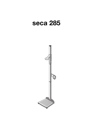
seca 285
English English CONTENTS 1. Full certification... 67 6. Operate scales... 89 2. Description of device... 68 2.1 Congratulations!... 68 2.2 Intended use... 68 3. Safety information...68 3.1 Basic safety precautions... 68 3.2 Safety information in this manual...69 3.3 Handling (rechargeable) batteries... 70 4. Overview... 71 4.1 Controls... 71 4.2 Display elements... 74 4.3 Information on rating plate... 75 4.4 Menu structure for multifunctional display... 76 4.5 Menu structure of the head slide... 77 5. Before you get started …... 78 5.1 Scope of supply... 78 5.2 Assembling the device... 79 Install second column element . 79 Install the multifunctional display . 80 Install the third column element. 81 Installing the push-in scale... 82 5.3 Set up device...82 5.4 Transporting the device... 83 5.5 Connecting the power supply . . 84 Insert batteries... 84 Connect the power supply unit . 84 5.6 Calibrate head slide... 85 Automated calibration... 85 Calibrating manually... 87
6.1 Weigh... 89 Start weighing... 89 Weigh babies/toddlers (2 in 1). . 89 Continuous display of measured result (HOLD)... 90 Enter patient data (input)... 91 Enter patient's gender... 92 Determine Body Mass Index (BMI)... 92 Determine Body Fat Rate (BFR) . 93 Transmit measured results to wireless receivers... 95 Print measured results... 95 Delete saved values (clear)... 95 Automatic switchover of weighing range... 96 Switch off scales... 96 6.2 Additional functions (menu)... 97 Navigate within the menu... 97 Delete values automatically (AClr)... 98 Switch between BMI and BFR (body)... 99 Set display backlighting (LCd) . . 99 Enter height manually (HGHt) . 100 Permanently save additional weight (Pt)... 100 Activate Autohold function (AHold)... 101 Activate acoustic signals (bEEP)... 102 Select attenuation (Fil)... 102 Restore factory settings (rESEt) . 103
• 65
7. Operate head slide... 104
8.2 Operate measuring station in a wireless group (menu) . . . 112 Set up wireless group (Lrn) . . . 113 Activate automatic transmission (ASend)... 115 Enable/disable wireless module (system)... 116 Select print option (APrt)... 116 Set time (Time)... 117
7.1 Measure height... 104 Start measuring height... 104 Continuous display of measured result (Hold)... 105 Perform relative measurements (zero)... 105 Transmit measured results to wireless receivers... 106 Switch off head slide... 106 9. Cleaning... 117 7.2 Additional functions (menu). . . 107 10. What to do if …?... 118 Navigate within the menu... 107 10.1 Faults and their correction . . 118 Activate acoustic signals 10.2 Change the batteries of the (bEEP)... 108 head slide... 121 Restore factory settings (rSEt). 108 Set display backlighting (LCd) . 109 11. Maintenance/Recalibration... 121 Switch over length units (Unit). 110 11.1 Information about 8. The seca 360° wireless network . . 111 maintenance and recalibration... 121 8.1 Introduction... 111 11.2 Check calibration counter seca wireless groups... 111 reading... 122 Channels... 112 Detection of devices... 112 12. Technical data... 123 12.1 General technical data... 123 12.2 Weighing data... 124 13. Accessories... 124 14. Disposal... 125 14.1 Disposal of device... 125 14.2 Batteries... 125 15. Warranty... 125
66 •
English
1. FULL CERTIFICATION With products from seca you are not only purchasing technology developed over a century, but also quality that has been validated by official bodies, the legal system and relevant institutes. seca products comply with European directives, standards and national laws. With seca you are buying into the future. The products in this user manual comply with the legislation governing medical devices, i.e. with directives 93/42/EEC and 2007/47/EC issued by the Council of the European Community, which is embodied throughout Europe in its national laws. Scales bearing this symbol comply with European Directive 2009/23/EC on Non-Automatic Weighing Instruments. seca scales with this symbol comply with the stringent quality and technical requirements applicable to calibratable scales.
M
Scales bearing this symbol comply with the stringent requirements of Class III of the directive and can be used for medical measurements which are subject to calibration.
09 0109 0123
Products bearing this symbol fulfil the following directives and standards • Directive 2009/23/EC on Non-Automatic Weighing Instruments. • Directives 93/42/EEC and 2007/47/EC on Medical Devices • EN 45501 on the Metrological Aspects of NonAutomatic Weighing Instruments. seca’s professionalism has also been officially recognised. The certificate from TÜV Product Service, the body responsible for medical devices, confirms that as a manufacturer of medical devices, seca rigorously complies with the stringent legal requirements. seca’s quality assurance system covers the development, production, distribution and servicing of medical scales and measuring systems. seca contributes to environmental protection. We are anxious to preserve our natural resources. This is why we strive to save packaging material where practical. And what is left over can be conveniently disposed of locally via Germany's Dual System recycling programme. • 67
2. DESCRIPTION OF DEVICE 2.1 Congratulations! By purchasing the seca 285 measuring station you have acquired an extremely accurate and robust device. For more than 170 years, seca has devoted its experience to health care and, as the market leader in many countries, is constantly setting new standards with its innovative weighing and measurement developments.
2.2 Intended use The seca 285 measuring station is mainly used in hospitals, doctors' surgeries and inpatient care facilities, in accordance with national regulations. The measuring station is used to determine height and weight. Wireless transmission of the height to the multifunctional display enables automated calculation of the Body Mass Index (BMI) and Body Fat Rate (BFR). The seca 360° wireless network allows the measured results to be transmitted wirelessly to a seca wireless printer or a PC equipped with the seca analytics 105 software and the PC equipped with the seca 360° Wireless USB adapter 456.
3. SAFETY INFORMATION 3.1 Basic safety precautions • Please take note of the information in this user manual. • Keep the user manual with the declaration of conformity in a safe place. • Ensure that the device is positioned securely on a flat and stable surface. • Do not expose the device to any violent impacts. • Do not place any sharp-edged objects on the glass plate of the base of the device. This could cause scratches, cracks and flaked or chipped off material. Such damage can cause the glass plate to break.
68 •
English • Regularly check the glass plate of the base of the device for scratches, cracks and chipped areas. If you find such damage, have the glass plate replaced with a new one. • Lay the mains cable so that there is no risk of tripping. • Only use the type of battery specified (see “Insert batteries” on page 84). • Have the scales serviced and recalibrated regularly (see “Maintenance/Recalibration” on page 121). • Make sure that maintenance and repair are only carried out by an authorised service partner. You can find your local service partner at www.seca.com or send an e-mail to service@seca.com. • Make sure you only use genuine seca accessories and spare parts. Otherwise the warranty provided by seca will become null and void. • Make sure RF equipment such as mobile phones is kept at a minimum distance of approx. 1metre to prevent incorrect measurements or interference with the wireless transmission.
3.2 Safety information in this manual DANGER! Used to identify an extremely hazardous situation. If you fail to take note of this information, serious irreversible or fatal injuries will occur. WARNING! Used to identify an extremely hazardous situation. If you fail to take note of this information, serious irreversible or fatal injuries may result. CAUTION! Used to identify a hazardous situation. If you fail to take note of this information, minor to moderate injuries may result. ATTENTION! Used to identify possible incorrect usage of device. If you fail to take note of this information, you may damage the device or the measured results may be incorrect. NOTE Includes additional information about use of the device. Safety information • 69
3.3 Handling (rechargeable) batteries The device is supplied with 4 batteries, type AA (Mignon). This type of battery is not rechargeable. Please take note of the following safety information. WARNING! Personal injury with improper handling.
Batteries contain harmful substances which may explode if not handled properly. − Do not try to recharge such batteries. − Do not expose (rechargeable) batteries to heat. − Do not burn (rechargeable) batteries. − If acid is leaking out, avoid contact with the skin, eyes and mucous membranes. Rinse affected areas with plenty of clean water and seek medical help at once. ATTENTION! Damage to device and malfunctions with improper handling
− Only use the type of (rechargeable) battery specified (see “Insert batteries” on page 84). − When replacing (rechargeable) batteries, always replace a complete set at a time. − Do not short-circuit (rechargeable) batteries. − If you do not use the device for a long period of time, remove the batteries (incl. rechargeable batteries). This prevents acid from leaking into the device.
70 •
English
4. OVERVIEW 4.1 Controls
6 7 5
8
4 9 3 2 10
1
11 12
19 18 17 16 15 14 13 20 21 23 22
Overview • 71
No. 1 2 3 4
5
Control Head slide Keypad, head slide Frankfurt measure Display, head slide Battery compartment, head slide
6
7
8
9
Brake button
10
Multifunctional display
11
72 •
Function Control for determining height Controls for performing length/height measurements and for configuring the device Pull-out ruler for aligning the head according to the socalled “Frankfurt Horizontal”. Display element of the head slide for measured results and for configuration Designed to take battery pack with 4 type AA batteries (mignon), 1.5 V Start key, head slide: Switch head slide on and off Arrow key (hold/zero) • During measuring - Press briefly: activate Hold function - Hold down: set zero point • In the menu: - Select submenu, select menu item - Set value (press briefly: value is changed by 1, press for longer time: value is changed until key is released) Enter key (send/print): • During measuring (if wireless network is set up) - Press briefly: Send measured result to ready to receive devices (multifunctional display, wireless printer, PC with USB wireless module) - Hold down: print out measured result (wireless printer) • In the menu: - Confirm selected menu item - Save set value • Holds the head slide in position • Pressed to move the head slide Central control and display element Arrow key send • During weighing (if wireless network is set up) - Send measured result to receive-ready devices (wireless printer, PC with USB wireless module) • In the menu: - Select submenu, select menu item - Increase value (press briefly: value is increased by 1, press for longer time: value is increased until key is released)
English No.
Control
12
13
14
Function Arrow key print • During weighing (if wireless network is set up) - print out measured result (wireless printer) • In the menu: - Select submenu, select menu item - Reduce value (press briefly: value is reduced by 1, press for longer time: value is reduced until key is released) Enter key (input): • During weighing - Enter patient data (age, gender, PAL) • In the menu: - Confirm selected menu item - Save set value menu key: • During weighing - Call up control panel menu. • In the menu: - Press briefly: go back one menu level - Hold down: exit menu
15
Start key, multifunctional display: Switch multifunctional display and scales on and off
16
clear key: Clear manually entered data or data received wirelessly (patient data, length/height, BMI, BFR)
17
gender key: Enter gender of patient
18
2 in 1 key: Start the 2 in 1 function for weighing babies and toddlers
19
hold key: Activate the hold function
20 21 22 23
Spirit level Casters Power connection Foot screw
Indicates whether the device is horizontal 2, for transporting scales over short distances For connecting the power supply unit 4 screws, for precise alignment of device
Overview • 73
4.2
Display elements
A B
C D E A
Symbol
Meaning
A
Battery power low.
B
Weighing range currently in use 1: More precise weight indication with lower load-bearing capacity 2: Maximum load-bearing capacity
C
Non-calibratable function active
D
Patient's gender
E
Operation with power supply unit
74 •
English
4.3 Information on rating plate Text/Symbol Model Type Ser.No.
Meaning Model number Type designation Serial number Refer to user manual Type B electromedical device Class II fully-insulated appliance For USA: device licensing number issued by the US Federal Communications Commission (FCC) For Canada: device licensing number issued by the Industry Canada authority
FCC ID
IC
Device complies with EC standards and directives. Symbol of the FCC (USA) Operate the device with direct current only, note the polarity of the device plug Do not dispose of device in household waste
Overview • 75
-
+
4.4 Menu structure for multifunctional display Additional functions are available in the device's menu. This allows you to optimally configure the device to suit your own needs (details from page 97 and from page 113). • Channel 1 (C1) rF*
Learn
Group (ID)
• Channel 2 (C2) • Channel 3 (C3)
Autosend
• on • off
System
• on • off
Autoprint
• HI • MA • HI_MA • off
Time
• Year • Month • Day • Hour • Minute
Stop
Reg. Devices (Mo)
*seca 360° wireless network:
Reset Autoclear
• on • off
Body
BMI
- 1 PC mit USB-Funkmodul
BFR Duration
• Short • Long • Permanent
Brightness
• 50 % • 100% • off
Pre-Tara
PT Weight
Net Weight
Autohold
• on • off
Beep
Press
• on • off
Hold
• on • off
LCD
Height
Filter
•0 •1 •2
Group (ID): seca 360° wireless: *Funknetzwerk Max. 3 seca wireless groups: 0, 1, 2 Group (ID): Maximum configuration per Max. drei seca Funkgruppen: 0, 1, 2 wireless group: Maximal-Konfiguration pro Funkgruppe: - 1 set of baby scales --1 1 Babywaage set of personal scales length measuring device --1 1 Personenwaage wireless printer --1 1 Längenmessstab - 1 PC with USB wireless module - 1 Funkdrucker Channel (C1, C2, C3): - Three channels per wireless Kanal (C1, C2, C3): group (in total 9 channels) -3 Kanäle pro Funkgruppe ( insg. 9 Kanäle) - Channel numbers: 0 - 99 -Kanalzahlen: - Only use 0-99 each channel number -Jede Kanalzahl nur einmal verwenden once - Recommended 30 -Empfohlener Abstand: spacing: 30 Example of configuration: Beispiel-Konfiguration: - Group 0: C1 0, C2 30, C3 60 - Gruppe 0: C1 0, C2 30, C3 60 - Group 1: C1 10, C2 40, C3 70 - Gruppe 1: C1 10, C2 40, C3 70 - Group 2: C1 20, C2 50, C3 80 - Gruppe 2: C1 20, C2 50, C3 80 (Note: no spaces in display) (Hinweis: Im Display keine Leerzeichen)
Devices detected (Mo): Erkannte Geräte (Mo): - 1: Personal scales --1:2: Personenwaage Length measuring device --2:3: Längenmessstab Wireless printer --3:4: Funkdrucker PC with USB wireless module scales --4:7: PCBaby mit USB-Funkmodul - 7: Babywaage
Navigation: Navigation: Call menu: Menüup aufrufen:
76 •
English
4.5 Menu structure of the head slide Additional functions are available in the device's menu. This allows you to optimally configure the device to suit your own needs. Details are give from page 107 and from page 113.
• on Beep
• off
CAL
No Yes
Auto
Learn
Group (ID)
• Channel 2 (C2)
• on
• Channel 3 (C3)
• Channel 1 (C1) rF
Autosend
Stop
Reg. Devices (Mo)
• off • on
System
• off • on
Autoprint
• off
Time
• Year • Month • Day • Hour • Minute
Duration
• Short • Long
Brightness
• 50 % • 100% • off
Reset
LCD
Unit
• cm • ft:in
End
Navigation: Call up menu:
Overview • 77
5. BEFORE YOU GET STARTED … 5.1 Scope of supply c
b
d
a e f g h i j k n o No. a b c d e f g h i j k l m n o
78 •
m
l
Component Base, preassembled - First column element - Head slide with Frankfurt measure Column element Threaded rod Upright connector End cap Elongated nut Plain washer Nut Decorative cap Hexagon socket head screws Cable clips Multifunctional display with connection cable Battery holder with 4 batteries, size AA Push-in scale Power supply unit Calibration rod, not illustrated User manual, not illustrated Cover, Frankfurt measure, not illustrated Toolkit, not illustrated
Qty. 1 2 2 1 1 1 1 1 1 2 2 1 1 1 1 1 1 1 1
English
5.2 Assembling the device The first column element and the head slide are already installed on the base of the device in the factory. Perform the remaining assembly with the assistance of another person. Due to the large overall height, we recommend placing the components on the floor and not uprighting the device until it is fully assembled. Proceed as follows.
Install second column element
To connect the column elements, proceed as follows: 1. Screw a threaded rod hand-tight into the elongated nut of the first column element. 2. Slide an column element over the threaded rod onto the first column element. ATTENTION! Damage to device due to assembly errors
If the upright connector and cover cap are mixed up, the device cannot be assembled as intended. − When installing the second column element, ensure that you use the upright connectors (see “Scope of supply” on page 78). 3. Position the upright connector on the second column element so that the threaded rod protrudes from the hole of the upright connector. 4. Screw an elongated nut onto the threaded rod. 5. Tighten the elongated nut.
Before you get started … • 79
Install the multifunctional display
The multifunctional display is hooked into the groove of the column element and fixed with a clamping screw. The installation height is freely selectable. 1. Insert the T-slot nut of the multifunctional display into the groove of the second column element.
2. Tighten the two hexagon socket head screws to fix the multifunctional display in the required position. 3. Guide the connection cable of the multifunctional display into the groove of the column element up to the base of the device. 4. Pull the connection cable through the hole in the base of the device. ATTENTION! Malfunction due to installation errors.
If the cables are installed so that they are subjected to large mechanical stress, faulty displays and failure of the display can result. − Lay all cables so that they are not bent too tight and the plugs are not kinked. 5. Wind the free end of the connection cable onto the cable winding in the base.
6. Plug the connection cable plug into the matching socket of the weighing platform.
80 •
English 7. Use the two cable clips to fix the connection cable into the groove of the column element.
8. Swivel the multifunctional display so that you can easily read it.
Install the third column element
To connect the column elements, proceed as follows: 1. Screw a threaded rod hand-tight into the elongated nut of the second column element. 2. Push the column element over the threaded rod onto the upright connector of the second column element. 3. Position the end cap on the second column element so that the threaded rod protrudes from the hole of the end cap. 4. Place the plain washer on the free end of the threaded rod. 5. Place the nut on the free end of the threaded rod. 6. Tighten the nut. 7. Place the decorative cap on the nut.
Before you get started … • 81
Installing the push-in scale
ATTENTION! Incorrect measurements due to installation errors
If the push-in scale is installed incorrectly the head slide cannot determine any usable readings. − Align the push-in scale so that the printing remains visible when the scale is pushed into the groove. − Align the push-in scale so that the area which shows the product number forms the bottom end. − Ensure that the push-in scale latches into position under the end cap. •
Push the push-on scale into the groove in the side of the column elements until the scale latches into position under the end cap.
5.3 Set up device ATTENTION! Incorrect measurement with force shunt
Correct measurements cannot be taken if the patient's weight is not fully positioned on the weighing area. − Set up the device so that it only makes contact with the ground via the foot screws. − Set up the device so that the weighing area does not touch any other objects. − While you are weighing, ensure that the patient does not touch the upright of the device. 1. Place the device on a flat, stable surface.
82 •
English Air bubble Spirit level
2. Align the device by turning the foot screws. The air bubble in the spirit level must be precisely positioned in the middle of the circle.
Foot screw 3. Tighten the thumbscrews in the direction of the arrow. The foot screws are secured against adjustment.
Thumbscrews
5.4 Transporting the device The device is equipped with two castors, which enable it to be transported over short distances. CAUTION! Risk of injuries and damage to the device
The device must be tilted. The large overall height of the device can result in injuries and damage to the device. − Ensure that there are no other persons in the immediate vicinity. − Ensure that there are no objects in the immediate vicinity. 1. Unplug the power supply unit from the socket. 2. Tilt the device backwards until it can freely move on the castors. 3. Upright the device. 4. Plug the power supply unit into the socket.
Before you get started … • 83