Somanetics
INVOS Clinical and Inservice Guide Dec 2012
Clinical and Inservice Guide
2 Pages

Preview
Page 1
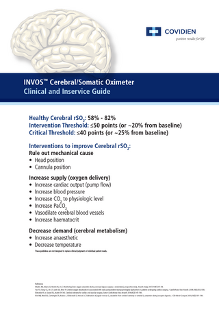
INVOS™ Cerebral/Somatic Oximeter Clinical and Inservice Guide Healthy Cerebral rSO2: 58% - 82% Intervention Threshold: ≤50 points (or ~20% from baseline) Critical Threshold: ≤40 points (or ~25% from baseline) Interventions to improve Cerebral rSO2: Rule out mechanical cause • Head position • Cannula position
Increase supply (oxygen delivery) • Increase cardiac output (pump flow) • Increase blood pressure • Increase CO2 to physiologic level • Increase PaCO2 • Vasodilate cerebral blood vessels • Increase haematocrit Decrease demand (cerebral metabolism) • Increase anaesthetic • Decrease temperature These guidelines are not designed to replace clinical judgment or individual patient needs.
References Murkin JM, Adams SJ, Novick RJ, et al. Monitoring brain oxygen saturation during coronary bypass surgery: a randomized, prospective study. Anesth Analg. 2007;104(1):51-58. Yao FS, Tseng CC, Ho CY, Levin SK, Illner P. Cerebral oxygen desaturation is associated with early postoperative neuropsychological dysfunction in patients undergoing cardiac surgery. J Cardiothorac Vasc Anesth. 2004;18(5):552-558. Edmonds HL Jr, Ganzel BL, Austin EH 3rd. Cerebral oximetry for cardiac and vascular surgery. Semin Cardiothorac Vasc Anesth. 2004;8(2):147-166. Kim MB, Ward DS, Cartwright CR, Kolano J, Chlebowski S, Henson LC. Estimation of jugular venous O2 saturation from cerebral oximetry or arterial O2 saturation during isocapnic hypoxia. J Clin Monit Comput. 2000;16(3):191-199.
HOW TO APPLY INVOS™ SENSORS 1) Remove any debris from patient’s forehead using alcohol wipe located with the sensor. 2) Ensure patient’s skin is completely dry. 3) If using a BIS™ sensor, apply BIS™ sensor first, ensuring the sensor runs low to the patients eyebrow. 4) Remove the protective backing from sensor and apply one sensor each to left and right side of forehead, ensuring the edges of sensor are sealed to prevent light from entering. Do not place sensor in the middle of forehead,over hair or broken skin. 5) Secure the sensor cable to a fixed object using strain relief clips.
HOW TO SET UP THE INVOS™ SYSTEM 1) Plug INVOS™ into power source and ensure blue light illuminates. 2) Connect pre-amp to INVOS™ monitor 3) Connect reusable sensor cables to pre-amplifier. Use colour coding e.g. 1 1 2 2 4) Connect left sided INVOS™ sensor to reusable cable “1” and right sided INVOS™ sensor to cable “2”
HOW TO SET UP INVOS™ MONITOR 1) Turn power ON by selecting the green ON/OFF key. Check both blue and green light illuminates. 2) If a new patient, use the press button located at the bottom of the monitor to select “new patient.” 3) Select <--, -->, and NEXT ROW to scroll through the characters and SELECT to enter highlighted character. 4) When entry is complete, select DONE
HOW TO SET A PATIENT BASELINE 1) Press HOME key (bottom right hand side) to display the main screen. 2) Press button below “baseline menu.” 3) Press button below “set baselines” 4) The set baseline will appear in green below rSO2 value. 5) Set Baseline prior to Induction.
COVIDIEN, COVIDIEN with logo, Covidien logo and positive results for life are U.S. and internationally registered trademarks of Covidien AG. Other brands are trademarks of a Covidien company. © 2013 Covidien AG or its affiliate. All rights reserved. PM 165-12-12
Covidien Pty Ltd 166 Epping Road, Lane Cove NSW 2066 Australia (t) 1800 252 467
Covidien New Zealand Limited Central Park Corporate Centre Level 3, Building 5, 666 Great South Road, Penrose, Auckland 1051 New Zealand (t) 0508 489 264
www.covidien.com