Owners Manual
28 Pages
Preview
Page 1
SPORTSART C531U UPRIGHT BIKE
TABLE OF CONTENTS 1. INTRODUCTION... 1 2. IMPORTANT SAFETY PRECAUTIONS ... 2 3. ASSEMBLING YOUR BIKE List of Parts... 4 Unit Assembly Procedure... 6 Seat Adjustment Procedure...12 Seat Forward/Backward Adjustment... 13 4. UNDERSTANDING THE C531U DISPLAY CONSOLE Display Windows... 14 Operating the C531U Bike... 17 Program Functions... 20 Internal Settings... 22 5. USER PARAMETER SETTING... 24 6. MAINTAINING THE BIKE...25 7. GUIDELINES FOR EXERCISE How long should I exercise ... 25 How often should I exercise... 25 8. TROUBLESHOOTING Error Messages... 26 9. WIRING SCHEMATIC... 27
SPORTSART C531U UPRIGHT BIKE INTRODUCTION Congratulations on purchasing one of the finest pieces of exercise equipment on the market today, the SportsArt C531U Upright Bike. Constructed of high quality materials and designed for years of trouble-free usage, the C531U will be an integral part of your fitness regimen. Before using your C531U bike, we recommend that you familiarize yourself with this Owner's Manual. Whether you are a first time user of an upright bike or a seasoned "pro," understanding the correct use of the equipment will enhance your ability to achieve your exercise goals safely and successfully.
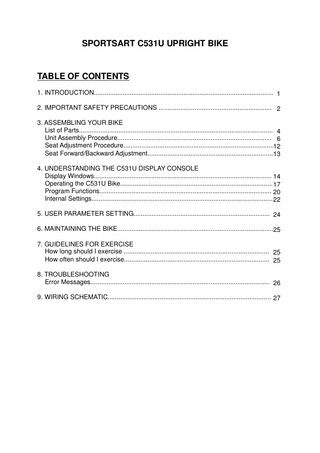
Cup holder Display Handlebar mount cover
Handlebar
Hand touch read-out sensor Pedestal
Upper cover Seat bottom Pedestal cover Seat post cover Side cover
Seat forward adjust lever
Pedal
Front foot cover Crank
Rear support cover
Lower frame Leveler
1
Your SportsArt bike was designed and built for optimum safety. However, certain precautions apply whenever you use your bike. Please read the entire manual before assembly and operation. Also, please note the following safety precautions:
IMPORTANT SAFETY PRECAUTIONS Please read and observe the following safety guidelines: ‧Keep this owner's manual for future use and reference. ‧Read this owner's manual and follow the instructions. ‧Assemble and operate the bike on a solid, level surface. ‧Never allow children on or near the bike. ‧Check the machine before every use. Make sure all parts are assembled, and all nuts and bolts are tightened. Do not use the machine if the unit is disassembled in any way.
Warning ‧Keep your hands away from moving parts. ‧Wear proper workout clothing. DO NOT wear overly loose clothing. Do not wear shoes with leather soles or high heels. Tie all long hair back. ‧Do not rock the unit from side to side and take care when mounting and dismounting the unit. ‧Do not stand on the unit.
2
‧Do not use accessories that are not specifically recommended by the manufacturer as these might cause injuries or cause the unit to fail. ‧Allow sufficient space on both sides of the bike for users to mount and to dismount the unit. ‧If any parts fail or are defective, please stop your workout immediately and contact your authorized dealer for repairs. ‧Work within your recommended exercise level; DO NOT work to exhaustion. ‧If you feel any pain or abnormal sensations, STOP YOUR WORKOUT. Consult your physician immediately. ‧The weight limit for this bike is 150 kgs (330 lbs).
Caution Before beginning any exercise program, you should consult with your doctor. It is recommended that you undergo a complete physical examination.
SAVE THESE INSTRUCTIONS
3
ASSEMBLING YOUR BIKE Thank you for purchasing our product. Even though we go to great efforts to ensure the quality of each product, occasional errors and/or omissions do occur. Please contact your dealer if you find this product to be defective or missing a part. Please read this owner's manual and follow the instructions. IMPORTANT: The packing for this bike was designed to protect it during shipment. Please store the original packing in a safe place in case you need to ship the unit in the future.
LIST OF PARTS Before assembling your bike, make sure that you have all of the following items. 1. Pedestal 2. Pedestal cover 3. Right pedal 4. Main frame 5. Rear support 6. Rear support cover 7. Left pedal 8. Seat bottom 9. Handlebar mount lower cover 10. Handlebars 11. Handlebar mount upper cover 12. Hardware kit 1-Open double end wrench, 1 pc 2-L-shaped Allen wrench (M5), 1 pc 3-L-shaped Allen wrench (M6), 1 pc 4-Screwdriver handle (green), 1 pc 5-Double-ended screwdriver stem, 1 pc 6-Round head Phillips screws, 5 pc 7-Screw inserts, 6 pc
4
1. Pedestal 2. Pedestal cover 3. Right pedal 4. Main frame 5. Rear support 6. Rear support cover
7. Left pedal 8. Seat bottom 9. Handlebar mount lower cover 10. Handlebars 11. Handlebar mount upper cover 12. Hardware kit
5
Unit Assembly Procedure STEP 1. For the following, please refer to Figure 1. Secure the rear support bar to the unit frame. Press screw inserts E into the holes. Loosen screws A, B, C, D to make room for the rear support cover. Slide the rear support cover into place. Then secure those screws.
Fig.1 Note: Hold the rear support cover at a 5-degree angle while inserting it into the frame. Press lightly at G to insert the top into both sides of the cover. When the top has entered the side covers, then slide the cover straight onto the support bar as shown in Figure 2.
Fig.2
6
STEP 2.
First slip the pedestal cover onto the pedestal. Position the data cable for safety. Then insert the pedestal onto its mount. Lightly tighten bolts A into the lower holes (at position D) to secure the pedestal. Do not fully tighten these bolts. Pull the pedestal downward until the other holes come into place and bolts can be secured. See Figure 3. Tighten bolts in position C, as shown in Figure 4. Then secure bolts in positions A and B, as shown in Figure 4. Connect data cable connectors, then insert the cable into the pedestal, as shown in Figure 5. Place the pedestal cover in place to meet the top cover, as shown in Figure 6.
Fig.4 Fig.3
Fig.6
Fig.5
7
STEP 3. In this step, be careful not to pinch the hand touch read-out (HTR) wires. Hold the handlebars in place on the frame while securing the handlebar bolts. Connect HTR wires. Then secure the upper and lower handlebar mount covers. See Figures 7- 9.
Fig.7
Fig.8
Fig.9
8
STEP 4. Be very careful in securing pedals to the pedal cranks. Otherwise, pedals and crank threads can easily become stripped and must be replaced. Note that left and right side designations refer to the user's left and right sides, as the person exercises on the bike. Put the pedal marked "R" on the right crank fitting. Turn the pedal stem clockwise by hand until you feel it smoothly thread into place. Then use the pedal wrench to secure the pedal firmly on the crank. Put the pedal marked "L" on the left crank. Turn the pedal stem counterclockwise by hand until you feel it smoothly thread into place. Then use the pedal wrench to secure it firmly in place on the crank. See Figure 10.
Fig.10
9
STEP 5. Secure the seat bottom into place. See Figure 11.
Flat washer Spring washer Nut Fig. A
Fig.11
10
STEP 6. Level the bike as follows to ensure that it does not wobble. Rotate rubber leveler feet up or down as needed to stabilize the bike. Then rotate leveler nuts upward, against the frame, to secure this position. See Figure 12.
Fig.12
11
Seat Adjustment Procedure To raise the seat height, turn the seat adjustment knob A counterclockwise to loosen it, then pull the seat up. See Figure 13.
Fig.13
To lower the seat height, do the following: 1. Pull the seat adjustment knob A out, toward the pedestal, then push the seat down. 2. Release the adjustment knob when the seat is at the proper position. 3. Turn the adjustment knob clockwise to secure it in place. See Figure 14.
Fig.14
12
Seat Forward/Backward Adjustment 1. Push the seat adjustment lever downward as shown in Fig. 15. 2. Move the seat bottom forward or backward as desired. Then pull the seat adjustment lever upward to secure the seat in place. See Fig. 16.
Fig.15
Fig.16
13
UNDERSTANDING THE C531U DISPLAY CONSOLE Display Windows The C531U is designed for user convenience. With better feedback about your workout, you get better results. The following explains the display key and window functions. Please read this manual, understand the display functions, and thereby get optimum enjoyment and benefit from this product. 65% HR TARGET
HEART RATE
80% HR TARGET
BODY AREA LED
DOT MATRIX WORKOUT ILLUSTRATION
SCAN INDICATOR
FEEDBACK WINDOW
EXERCISE PROGRAMS KEYS
14
Display Function Overview ˙ Windows: ■ 65% HR TARGET - shows the optimum heart rate zone for weight loss. ■ HEART RATE - shows actual heart rate. ■ 80% HR TARGET - shows the optimum heart rate for cardio workout. ■ WORKOUT ILLUSTRATION - shows workout profiles and workout prompts. ■ FEEDBACK WINDOW - shows workout prompts and workout feedback. ■ LEDs -light to indicate active programs, active feedback, scan mode, selection confirmation, and body areas being exercised. ˙ Basic Functions: CHANGE - Press the CHANGE key while exercising to view different workout feedback. Active feedback indicators light up. Top row: WORKOUT LEVEL, CALORIES, TIME, RPM. Bottom row: DISTANCE, CAL/HR, WATTS, SPEED. In SCAN mode, a different row of feedback information is displayed every six seconds, and the scan indicator flashes every second. If not in SCAN mode, the indicator LEDs remain lit. QUICK START - Press this key to start exercising without first entering user information. In QUICK START mode, time counts upward; values accumulate. START- Press this key to start exercising after inputting user information. EXERCISE PROGRAMS KEYS - When these indicators flash or during exercise, press an exercise program key to activate the related program. The related program indicator lights up. ENTER - After making a selection, press this key to confirm your choice. WORKOUT LEVEL (UP & DOWN) - Press these keys to adjust resistance level. Holding these keys makes resistance adjust up or down faster. STOP/HOLD TO RESET 1. In an exercise program, (A) If you entered an exercise program through QUICKSTART, press the STOP key to leave the program. (B) If you entered an exercise program through START key, press the STOP key to select another program. PROGRAM indicators flash.
15
2. In any circumstance, hold the STOP key for three seconds to go back to the start up banner screen.
Display Setting Ranges ˙ WORKOUT LEVEL (resistance): 1 ~ 20 ˙ TIME: 00~99:59; setting range: 5:00 ~ 99:00. (After 99:00, 0 appears) ˙ DISTANCE: 0.01-9999 Km/Mile ˙ CALORIES: 0~9999 K-CAL ˙ CAL/Hr (calories per hour): 0.0~999.9 K-CAL ˙ RPM (rotations per minute): 0~200 (countable) ˙ HEART RATE (range): 40-250 ˙WATTS: 0~9999 ˙SPEED: 0~55.9 Mile/H / 0~90 Km/H (1 Km=0.62137 Miles; 1 Mile=1.60935 Km) ˙ PROGRAMS: TRACK, HILL, RANDOM, INTERVAL, WT LOSS, CARDIO, ZONE TRAINER. ˙USER: Four user settings(including 11 alpha-numeric ID settings) ˙AGE: 10~99 ˙WEIGHT: 30 ~ 150 Kg or 66 ~ 330 LB
16
Operating the C531U Bike To start: Press the START key or press the QUICK START key, or simply start pedaling (over 30 RPM). The startup banner "SPORTSART-C531" appears. 1. QUICK START (A) At the startup banner, press the QUICK START key. Quick start mode uses the default assumption of a 35-year-old, 165-lb/75-Kg user to calculate calorie and other feedback values. Time counts upward. Resistance starts at level one and can be adjusted during exercise. (B) While exercising, press EXERCISE PROGRAM keys or ZONE TRAINER key to change exercise programs. Time counts upward. Resistance can be adjusted at any time. (C) When no one pedals on the bike, "PEDAL TO START" scrolls across the display every four seconds, after which the start up banner screen appears. (D) If no one pedals for 15 seconds, an energy saving mode is activated. It remains on until someone pedals over 30 RPM. (E) In energy saving mode, all LEDs extinguish except for the feedback window which shows the following: 一 一 一 一 (F) If no one pedals for two minutes, the unit automatically shuts off. 2. START Press START to take advantage of user age and weight in providing more accurate calorie counts and other information. This user information is saved in the unit's memory and the user's workout time, distance, and calorie expenditure accumulates. (A) The process to establish a user ID is as follows: 1.Selecting User ID ˙While the start up banner appears, press the START key. The display shows the previously used USER ID and that user's accumulated workout record. ˙ Every six seconds, the display shows different information, as follows: USER-1
17
TIMES - 25:05 DISTS - 15.8 CALS - 1020 ˙Use any <▲>or <▼>key to choose a user ID. Then press ENTER to confirm your choice. 2. To set up a personalized user ID ˙This function allows users to establish a user ID with up to 11 characters. ˙When a USER ID appears, press the CHANGE key continuously for three seconds to change the USER ID. The following appears: E
N
T
E
R
N
A
M
E
˙Press <▲▼> keys to choose an alphabetical character. Then press the ENTER key to confirm your selection. Use the same process again to choose and confirm more characters. When the user name is complete, hold down the ENTER key for three seconds to complete the process. ˙To revise or delete a USER NAME, choose the USER ID and hold down the CHANGE key for three seconds. To revise the ID, follow the steps above. ˙To erase accumulated workout information, press STOP and START keys simultaneously. User accumulated workout time, RPMs, and distance will disappear. (B) Age and Weight Settings 1. AGE setting range is 10 ~ 99. The default age is 35 years old. ˙Press <▲/▼>keys to select a user age. This user age becomes the basis for calculating target heart rate. 65% and 80% target heart rates represent recommended low and high heart rate targets. ˙Press the ENTER key to confirm your choice and proceed to set the user weight. 2. WEIGHT setting range is 66 ~ 330 LB / 30 ~ 150 KG. The default weight setting is 165 LB / 75 KG.
18
˙Press <▲/▼>keys to select a weight. User weight is the basis for the calorie expenditure calculation. ˙Press the ENTER key to confirm your choice and proceed to select your exercise program. (C) To select a workout program 1. Press the workout program key. The related PROGRAM indicator lights up. Then press the ENTER key to confirm your choice and proceed to the TIME setting. 2. When exercising, press the Zone Trainer key to enter the heart rate control (HRC) mode. (D) Time setting 1. Press the <▲>or <▼>key to select an appropriate duration for your workout. Then press the ENTER key to confirm your choice. (E) Changes during a workout 1. Resistance can be changed as you exercise. Time starts counting upward when you start pedaling. On the workout illustration, your present stage in the workout is represented by the flashing LED. 2. As you workout, you can activate another program. Time continues to accrue. 3. In USER mode, you can move from any workout program to another workout program while exercising. The accumulated values continue to accrue. 4. Please note: ZONE TRAINER has special rules which are described in the following section. (F) Cool Down When the workout time is reached, "ACCU DATA" appears. Accumulated data, including time/distance/calorie expenditure/average heart rate, appear. Then "COOL DOWN" appears as the unit enters a two-minute cool down period. When the unit counts down to "0:00", program indicators flash, and the "SELECT PROGRAM" prompt appears. Press the QUICK START key to immediately start exercising, or press START to reset user information.
19