STIHLER
ASTROPAD System Instructions for Use Rev 13 March 2015
Instructions for Use
47 Pages
Preview
Page 1
Instructions for Use
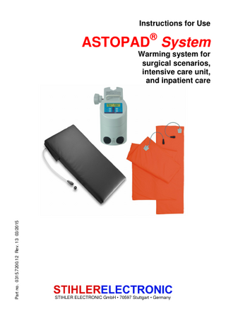
ASTOPAD® System
Part no. 0315.7200.12 Rev. 13 03/2015
Warming system for surgical scenarios, intensive care unit, and inpatient care
STIHLER ELECTRONIC GmbH • 70597 Stuttgart • Germany
To be completed by the user: Serial number Registration number Equipment location Start-up date
Manufacturer:
STIHLER ELECTRONIC GmbH Julius-Hoelder-Strasse 36 70597 Stuttgart GERMANY Tel. +49 (0) 711-720670 Fax +49 (0) 711-7206757 www.stihlerelectronic.de E-Mail: info@stihlerelectronic.de
STIHLER ELECTRONIC GmbH, Stuttgart, declares in sole responsibility that this product conforms to EC Directive 93/42/EEC on medical devices. Notified body: DEKRA Certification GmbH, registration number 0124.
Contents 1 Introduction ...4 1.1 INFORMATION ON THESE INSTRUCTIONS ...4 1.2 SPECIFICATION OF THE APPLICATION ...4 1.3 IMPORTANT SAFETY INFORMATION ...5 1.3.1 Dangers...6 1.3.2 Warnings ...6 1.3.3 Caution information ...9 1.3.4 Notices ...10
1.4 SYMBOLS ...11 1.5 CONFORMITY WITH INTERNATIONAL STANDARDS ...13 1.6 GUARANTEE CONDITIONS ...14 1.7 LIABILITY ...14 1.8 DISPOSAL OF THE EQUIPMENT ...14 1.9 RETURN OF A USED PRODUCT ...15 1.10 SERVICE INFORMATION ...15 2 Product description...16 2.1 INTRODUCTION ...16 2.2 TECHNICAL DESCRIPTION ...16 2.3 COMPONENTS OF ASTOPAD SYSTEM ...18 3 Operating states ...19 SWITCHING ON THE CONTROL UNIT ...20 STARTING THE HEATING PROCESS AT OUTPUT A AND/OR B ...21 SELECTING A NEW SET TEMPERATURE ...22 SWITCHING OFF AN OUTPUT (A OR B) ...23 SWITCHING OFF THE CONTROL UNIT ...23 SAVING A NEW INITIAL SET TEMPERATURE ...24 4 Installation ...24 4.1 INITIAL START-UP ...24 5 Start-up...25 5.1 PREPARATION FOR USE ...25 5.2 STARTING THE HEATING PROCESS ...28 5.3 SELECTING A NEW SET TEMPERATURE ...28 5.4 SWITCHING OFF AN OUTPUT ...28 5.5 AFTER USE ...29 5.6 CLEANING AND DISINFECTING ...29 6 Alarms and troubleshooting ...30 LOW TEMPERATURE ALARM “A1” ...31 OVERHEATING ALARM “A2” ...32 OVERHEATING ALARM SHUT-OFF ...33 TIME ALARM “A3” ...34 CABLE BREAKAGE ALARM “L” ...35 POWER FAILURE ALARM...36 7 Brief overview of operating states, messages, alarms ...37 8 Servicing ...39 8.1 PREVENTATIVE SERVICING ...39 8.2 REPEATED INSPECTIONS ...39 9 Technical data ...40 10 Ordering information...43 11 Guidelines and manufacturer’s declaration ...46
ASTOPAD SYSTEM Instructions for Use
1 Introduction
1 Introduction 1.1 Information on these instructions It is imperative that you read these instructions for use before using this product. Failure to follow the instructions for use can result in damage to the product or to other property and/or personal injury. These instructions contain important information on the safe use of ASTOPAD SYSTEM. Fully read the instructions for use, including the warning and caution information, before you use ASTOPAD SYSTEM. Failure to follow the warnings, cautions, and information on use can result in death or severe injury to the patient. The ASTOPAD SYSTEM patient warming system consists of an ASTOPAD DUO120 control unit and the applied parts ASTOPAD COV and ASTOPAD SOF. These instructions for use are directed towards trained healthcare personnel and persons in medical professions.
1.2 Specification of the application 1.2.1 Intended medical indications ASTOPAD SYSTEM can be used in pre-, peri-, and post-operative areas and serves as a prophylaxis against patient cooling and as hypothermia therapy. ASTOPAD SYSTEM can be used in rooms designated for medical purposes, such as the operating room, intensive care unit, anaesthetic recovery room, and patient room, in which there is a risk of patient cooling or when patients should be exposed to external heat. In addition to being used for adults and children in the aforementioned areas, ASTOPAD SYSTEM can also be used for prophylaxis against patient cooling and for hypothermia therapy in infants and toddlers. For infants and toddlers up to 90 cm in height, use only the applied parts ASTOPAD COV070 and ASTOPAD SOF7. From the variety of ASTOPAD SYSTEM applied parts that can be combined with the ASTOPAD DUO120 control unit, you can select the right product for every application in the above areas.
4
1 Introduction
ASTOPAD SYSTEM Instructions for Use
1.2.2 Contra-indications ASTOPAD SYSTEM is not intended for use in incubators, homecare or veterinary medicine. 1.2.3 Possible side effects No side effects are known for the use of ASTOPAD SYSTEM. 1.2.4 Intended patient group The height of the intended patient group must be at least 35 cm. Otherwise there are no other restrictions. 1.2.5 Intended users of the patient warming system Only medically trained professionals may put into use the patient warming system. Information on function and handling is found in these instructions for use. 1.2.6 Intended conditions for use The patient warming system may be used only in rooms designated for medical purposes. For the application of this product, the relevant and applicable hygiene rules for the use of medical devices apply.
1.3 Important safety information These instructions for use define and refer to the following safety information. DANGER Describes a maximum risk from a situation which, when not avoided, can lead directly to severe or fatal injuries. WARNING Describes a dangerous situation which, when not avoided, can lead to severe or fatal injuries. CAUTION Describes a dangerous situation which, when not avoided, can lead to mild to moderate injuries. NOTICE Describes a warning relating to material damage.
5
ASTOPAD SYSTEM Instructions for Use
1 Introduction
1.3.1 Dangers DANGER Explosion hazard! Do not use the ASTOPAD SYSTEM patient warming system in an explosionhazard environment or in the presence of flammable anaesthetics. 1.3.2 Warnings WARNING Risk of injury! • Read and observe all instructions, stickers, and accompanying documentation that came with the medical device. Failure to observe the instructions, including warnings and safety information, can result in incorrect handling, patient injury, user injury, medical personnel injury, damage to the device, or material damage. • Operate and service this equipment only in accordance with the procedures described in these instructions and with the applicable standards, rules, and guidelines. The manufacturer shall not be responsible for the safety of users or patients if any actions/procedures other than those published are carried out during operation, servicing, or repeated inspections. • Operating and servicing personnel must be appropriately trained and medically qualified. • If the OR table top is tilted (set through the longitudinal axis), there is a danger that the patient will slip off. The patient must be sufficiently secured against slipping before the OR table top is tilted or otherwise moved out of the horizontal position. • Due to the physicochemical properties of the disinfectants, ensure that the disinfectants do not collected beneath the patient. During use, the patient may not be moist or even wet when lying on the mattress. This presents a chemical burn hazard. • When RF surgical instruments or endocardial catheters are used, the patient must also be insulated according to regulations. This insulation may not be damp. The device manufacturer’s instructions for use must be observed at all times. • With transdermal drug applications (patches), the additional heat can increase the uptake of the drugs and lead to patient injury. • In the case of arterial occlusion, the ASTOPAD SYSTEM applied parts may not be used distal to this area. • Overheating of ischemic extremities can occur with the use of ASTOPAD SYSTEM applied parts.
6
1 Introduction
ASTOPAD SYSTEM Instructions for Use
WARNING Risk of injury! • ASTOPAD SYSTEM does not contain any parts the user can repair. Therefore, do not attempt to repair ASTOPAD SYSTEM yourself. Contact your local sales point. • When ASTOPAD COV applied parts are used as a top blanket, ensure that they do not obstruct the patient’s field of vision. • Do not use ASTOPAD SYSTEM until the following error conditions have been remedied through appropriate corrective action: - Damaged or worn cables, plugs, or device box. - Damaged casing, damaged or loose control panel, missing protective cover on mains switch. - Damaged outer cover of the applied parts. - Alarm testing equipment defective. No optical or acoustic alarm after the mains switch is switched on. (Self-test) - Switches that are loose or not operating correctly. - A system that has been exposed to mechanical impact or liquid ingress into internal electronic system components. - A system that has previously delivered an electric shock to a person. - A system that appears to be overheating. • If at least one of the applied parts in a system triggers or has triggered an alarm shut-off. • Have the equipment repaired if the self-test is not activated automatically after the mains switch is switched on and heating starts straight away. • The extension connection cable and the mains cable should not touch the patient and should not hinder the treating personnel. • Only persons authorised and qualified by the manufacturer may perform repairs to the equipment (e.g., replacement of mains connection cable). • Modifications to ASTOPAD SYSTEM are not permitted. WARNING Danger of overheating! For infants and toddlers up to 90 cm in height, use only the applied parts ASTOPAD COV070 and ASTOPAD SOF7.
7
ASTOPAD SYSTEM Instructions for Use
1 Introduction
WARNING Risk of infection! • Clean and disinfect the equipment after every use and before you return the equipment for repairs. • Route the extension connection cable between the applied part and control unit in such a way that the cable is protected from mechanical damage. Prevent the cables from coming into contact with the floor. WARNING Risk of decubitus ulcer! • Regardless of the treatment duration, aged, paralysed, comatose, and cachectic patients are particularly at risk for decubitus ulcers. They should therefore also be constantly examined at the critical locations by medical personnel. • Do not fold, bend, or operate in a folded condition the applied parts. • Do not place the patient on the connection block of the applied part. • When the ASTOPAD COV applied parts are used as an under-blanket, ensure that they are placed flatly underneath the patient, are secured, and will not crease. • ASTOPAD COV applied parts can be wrapped around the patient. However, make sure that the applied part will not form creases. WARNING Risk of electric shock! • To prevent the risk of an electric shock, connect this equipment only to a mains power supply with an earth conductor. Do not use mains adapters that interrupt the earth conductor. Do not open the ASTOPAD DUO120 casing. • If several pieces of equipment are combined or connected together (e.g., in multiple socket outlets), the sum of the leakage currents may not exceed the allowable limits (follow the respective national regulations). Observe the requirements as stipulated in IEC/EN 60601-1 regarding medical electrical equipment. • All electrical installations must conform to the applicable electrical standards and the specifications defined by the manufacturer. • Before every use, check to make sure that the ASTOPAD DUO120 control unit and the ASTOPAD SYSTEM applied parts are undamaged.
8
1 Introduction
ASTOPAD SYSTEM Instructions for Use
1.3.3 Caution information CAUTION Risk of injury! • The use of the ASTOPAD SYSTEM patient warming system must be carried out under the responsibility of a physician. • When installing the ASTOPAD DUO120 control unit on an infusion stand, observe the instructions from the infusion stand manufacturer regarding maximum load and overturning stability. • When ASTOPAD SYSTEM is used on the OR table, the OR table must be prepared according to the customary regulations and guidelines. • Never insert pointed or sharp objects into the applied parts or damage the surface of the parts in any other way. CAUTION Risk of hypothermia! • If the alarm shut-off of ASTOPAD SYSTEM is triggered at an output, the entire system will switch off. • If thermally conductive materials, such as water, gel, and similar substances, are used and were not pre-heated, the patient’s body temperature may lower as a result once the ASTOPAD SYSTEM applied parts are switched off. • When ASTOPAD SYSTEM is used, the patient’s body temperature must be monitored at regular intervals. • Controlling the temperature of ASTOPAD SYSTEM controls the temperature of the applied parts, but not the patient’s body temperature. • When this product is used in combination with other heat sources, an overheating alarm or an overheating alarm shut-off may occur on the ASTOPAD DUO120 control unit. CAUTION Risk of radio interference! • According to Standard IEC/EN 60601-1-2, medical electrical equipment requires special precautionary measures in regard to electromagnetic compatibility (EMC). Install and operate medical equipment according to the EMC information listed in the accompanying documentation. Portable and mobile RF communication equipment may have an impact on medical electrical equipment. • This equipment/system can produce radio interference and can interfere with the operation of equipment in close proximity. It may be necessary to take appropriate corrective action, such as a new direction, a new configuration of ASTOPAD SYSTEM, or shielding.
9
ASTOPAD SYSTEM Instructions for Use
1 Introduction
1.3.4 Notices NOTICE • The specified moisture resistance IPX2 for the ASTOPAD SYSTEM applied parts is ensured only when the connector - Is connected to a suitable extension cable. or - The attached protective cap is used. • Actions to avoid damaging the patient warming system: - Do not immerse the control unit and/or the connector for the connection cable in liquid. - Do not disinfect the system using steam (e.g., in autoclaves), hot air, or thermo-chemical cleaning solutions. • The customer is responsible for the proper packaging and labelling of returns. • The operator should not use any cleaning or decontamination methods other than those recommended by the manufacturer. • The specified defibrillation protection is ensured only when the applied part is connected to the extension connection cable and the control unit.
10
1 Introduction
ASTOPAD SYSTEM Instructions for Use
1.4 Symbols Where applicable, these symbols appear at the appropriate location on the patient warming system, on the packaging, on the identification plate, and in the accompanying documentation.
IPX 1 IPX 2
Defibrillation protected applied part type BF in accordance with IEC/EN 60601-1 Protected against falling water in accordance with IEC/EN 60529 (control unit) Protected against falling water in accordance with IEC/EN 60529 (applied parts) Observe the instructions for use. General warning/danger symbol
REF
Reference (part) number
SN
Serial number Alarm condition when yellow LED flashes OFF position of the mains switch ON position of the mains switch “Start” key: starts the heating process Temperature increase set value Temperature decrease set value Switches off the power failure alarm using the (only acoustic alarm switches off)
key.
Year of manufacture Manufacturer “SET” key: saves a new initial set temperature “Stop” key Margins of the heated area
11
ASTOPAD SYSTEM Instructions for Use
1 Introduction
Symbol on plug connector for potential equalisation in accordance with IEC/EN 60601-1 Electrical devices are recoverable waste and should not be disposed of in domestic waste at the end of their service life. Dry at low heat Boil-proof, delicate wash cycle Do not use chlorine bleach Do not iron Dry-cleaning possible, limited to mechanical stress This device conforms to EC Council Directive 93/42/EEC of 14 June 1993 concerning medical devices. The notified body, DEKRA Certification GmbH (registration number 0124), monitors the manufacturer’s quality management system. Additional information Tilt of the OR table top Acoustic alarm No acoustic alarm Notice for the position of the locking ring on the cable plug of the extension connection cable Symbol for the permitted temperature range for storage and transport Symbol for the permitted moisture range for storage and transport Symbol for the permitted atmospheric pressure range for storage and transport Transport with the arrows pointing up Keep dry Fragile, protect against impacts
12
1 Introduction
ASTOPAD SYSTEM Instructions for Use
1.5 Conformity with international standards Standard
Title
IEC/EN 60601-1
IEC/EN 60601-1-2
IEC/EN 60601-1-8 (applicable parts)
IEC/EN 80601-2-35
Medical electrical equipment – Part 1: General requirements for basic safety and essential performance Medical electrical equipment – Part 1-2: General requirements for basic safety and essential performance – Collateral standard: Electromagnetic compatibility – Requirements and tests Medical electrical equipment – Part 1-8: General requirements for basic safety and essential performance – Collateral standard: Alarm systems – General requirements, tests, and guidance for alarm systems in medical electrical equipment and medical electrical systems Medical electrical equipment – Part 2-35: Particular requirements for basic safety and essential performance of heating devices using blankets, pads, or mattresses and intended for heating in medical use.
Definitions according to IEC/EN 80601-2-35:
Term
Definition
Top blanket
Blanket for use on top of patient
Underblanket
Blanket for use underneath patient
Pad Mattress
Applied part of a heating element that may be bent, but not folded Applied part in a heating element that supports the patient’s entire body resiliently
ASTOPAD SYSTEM applied parts COV070/COV105/ COV150/COV155/ COV180/COV235 COV070/COV105/ COV150/COV180/ COV235 SOF4/SOF5/SOF7 SOF2
13
ASTOPAD SYSTEM Instructions for Use
1 Introduction
1.6 Guarantee conditions The guarantee period is 12 months. During this guarantee period the manufacturer will repair or replace free of charge all defects caused as a result of material or manufacturing errors. Other damage is not subject to this guarantee. The guarantee does not include cases of misuse or incorrect handling, use of force, or damage caused by normal wear and tear. This applies also to changes undertaken by persons who are not authorised by the manufacturer and to modifications to the original condition. If the equipment is damaged during the guarantee period, send the cleaned equipment to the nearest sales point or directly to STIHLER ELECTRONIC GmbH. The sender is responsible for any transport and packaging costs.
1.7 Liability The manufacturer shall be liable for the safety, reliability, and performance of the equipment only when all operating, servicing, and calibration procedures have been carried out by trained and qualified persons according to the procedures published by the manufacturer; when only original spare parts have been used to replace components as needed; when the assembly and completion of repairs have been carried out only by authorised persons or an authorised service centre; when the electrical installations satisfy the locally applicable regulations and the IEC/EN requirements; and when the equipment is used for its intended purpose and at a suitable location in accordance with the instructions for use. On request, STIHLER ELECTRONIC GmbH will provide service instructions that will allow properly trained and qualified persons to repair the parts of the equipment that the manufacturer has designated as reparable. The provision of technical documents or spare parts is not an authorisation from the manufacturer to open or repair the equipment.
1.8 Disposal of the equipment Electrical devices are recoverable waste and should not be disposed of in domestic waste at the end of their service life. Please follow the local rules for the disposal of used products, or send the cleaned and disinfected equipment with a corresponding note to STIHLER ELECTRONIC GmbH or your closest sales point. This will ensure the most cost efficient and proper disposal of your old equipment. Follow the national regulations on the disposal of medical products.
14
1 Introduction
ASTOPAD SYSTEM Instructions for Use
1.9 Return of a used product A report must be sent together with the equipment, detailing the precise reasons, circumstances, and, if known, the cause of the return. To prevent transportation damage, the equipment should be shipped either in the original packaging or in other, well-protected packaging. WARNING Risk of infection! Clean and disinfect the equipment after every use and before you return the equipment for repairs. NOTICE The customer is responsible for the proper packaging and labelling of returns.
1.10 Service information For service or technical support, please contact your local sales point or the following: STIHLER ELECTRONIC GmbH Tel. +49 (0) 711-720670 Julius-Hoelder-Strasse 36 Fax +49 (0) 711-7206757 70597 Stuttgart www.stihlerelectronic.de GERMANY E-Mail: info@stihlerelectronic.de
15
ASTOPAD SYSTEM Instructions for Use
2 Product description
2 Product description 2.1 Introduction ASTOPAD SYSTEM is the flexible and universal dry warming system for the operative, intensive care, and inpatient medical field. ASTOPAD SYSTEM consists of a control unit, which can be used to operate one or two applied parts independently of one another. While the applied parts ASTOPAD COV070/COV150/COV180/COV235 can be used as a top blanket or under-blanket, the applied part ASTOPAD COV155 is intended specifically for covering the patient’s upper body. All ASTOPAD SYSTEM applied parts can have direct skin contact (injured/uninjured skin) with the patient or are operated with an intermediate layer between the part and the patient. WARNING Danger of overheating! For infants and toddlers up to 90 cm in height, use only the applied parts ASTOPAD COV070 and ASTOPAD SOF7. The ASTOPAD SOF applied parts provide the best prophylaxis against decubitus ulcers thanks to the use of visco-elastic foam. The integrated heater provides the patient with additional warmth via the mattress and thus plays an important role in hypothermia prophylaxis. All ASTOPAD SOF applied parts are equipped with an antistatic cover. The ASTOPAD DUO120 control unit is used to control and monitor the contact surface temperature of the ASTOPAD SYSTEM applied parts.
2.2 Technical description ASTOPAD DUO120 is the control unit for ASTOPAD SYSTEM and is equipped with a universal attachment clip for attaching to an infusion stand. CAUTION Risk of injury! When installing the ASTOPAD DUO120 control unit on an infusion stand, observe the instructions from the infusion stand manufacturer regarding maximum load and overturning stability. The ASTOPAD DUO120 control unit has two outputs (device boxes) A and B (Fig. 1) for connecting ASTOPAD SYSTEM applied parts. The required temperature of the respective applied part can be selected in a range from 32.0 °C to 39.0 °C in 0.5 °C increments on the control panel of the control unit. Outputs A + B can be set and operated independently of one another. Optionally, the system can also be operated with only one of the outputs A or B occupied. The temperature for each output, A or B, is selected on the part of the control panel located above each output. 16
2 Product description
ASTOPAD SYSTEM Instructions for Use
The selected temperature for each output is shown individually in small font at the bottom of the control panel, and the actual current temperature of the applied part is displayed in large numbers above this. The ASTOPAD SYSTEM applied parts consist of an x-ray-permeable, highly flexible heating element, which is supplied with 24-volt extra-low voltage heating current from the control unit. The temperature is controlled by eight sensors attached to heating element. The ASTOPAD COV applied parts can be used as a top blanket for warming the patient from above and/or as an under-blanket for warming the patient from underneath. ASTOPAD SYSTEM can be used in rooms designated for medical purposes, such as the operating room, intensive care unit, anaesthetic recovery room, and patient room, in which there is a risk of patient cooling or when patients should be exposed to external heat. Together with the pressure-relieving gel pad ASTOGEL, the ASTOPAD COV applied part plays an important role in the prevention of hypothermia and decubitus prophylaxis in surgical scenarios. When placed on top of the ASTOGEL gel pad, ASTOPAD COV prevents patient cooling from a cold gel pad, and the heat generated will be conveyed to the patient directly after heating starts. A long warm-up time for the ASTOGEL gel pad is not needed. However, it should be noted that only a combination of ASTOPAD COV and ASTOGEL is permitted. The contact surface temperature can be set from 32.0 °C to 39.0 °C in increments of 0.5 °C. The safety of ASTOPAD SYSTEM and its applied parts is guaranteed by the following measures: • 8 temperature sensors • 2 independent overheating shut-offs • Cable breakage alarm • 2 independent time shut-offs • Optical and acoustic alarm signals • Overheating and low-temperature alarm if the contact surface temperature deviates from the temperature controller setting • Power failure alarm The heating-up period from 23.0 °C to a contact surface temperature of 37.0 °C for ASTOPAD SYSTEM applied parts is approximately 10 minutes.
17
ASTOPAD SYSTEM Instructions for Use
2 Product description
2.3 Components of ASTOPAD SYSTEM
Fig. 1 Components of ASTOPAD SYSTEM
No. Designation 1 Attachment clip 2 Control panel 3 Mains switch Output A 4 (device box) Output B 5 (device box) 6 ASTOPAD COV 7 ASTOPAD SOF 8 Connection cable
9 End cap
10
18
Extension connection cable
Description For safely attaching the ASTOPAD DUO120 control unit to an infusion stand Operating keys and temperature displays For switching on and off the control unit Plug connection between control unit and applied part Example of an ASTOPAD COV applied part Example of an ASTOPAD SOF applied part Connection cable for connecting to the extension connection cable The attached end cap is used to close off the end when an extension cable is not connected. It protects the contacts and guarantees the IPX2 moisture resistance. The extension connection cable is used to connect the ASTOPAD COV and SOF applied parts to the control unit.
3 Operating states
ASTOPAD SYSTEM Instructions for Use
3 Operating states
Fig. 2 Control panel components
No. Designation Actual 1 temperature A and B Set temperature 2 A and B 3
“Start” key A and B
“Temperature 4 increase” key A and B “Temperature 5 decrease” key A and B 6
“Start” LED (green) A and B
7 “SET” key “Alarm” LED 8 (yellow) 9
“Stop” key A and B
Description Displays the actual temperature of the applied part Displays the selected set temperature of the applied part Press this key to start the heating process. OR
Press this key to confirm a change made to the set temperature. Press this key to increase the set temperature in increments of 0.5 °C. You must press the “Start” 3 key to confirm any new set temperature value you select. Press this key to decrease the set temperature in increments of 0.5 °C. You must press the “Start” 3 key to confirm any new set temperature value you select. LED flashes when the heating process has not yet started. LED is solid when the heating process has started. Key for saving a new initial set temperature LED flashes and the acoustic alarm signal sounds when there is an alarm situation. Ends the heating process and switches off the respective output. Stop A cancels the power failure alarm!
19
ASTOPAD SYSTEM Instructions for Use
3 Operating states
The individual operating states are explained in the following section. This section contains a description of the user actions and the device responses for each operating state.
Switching on the control unit
Control panel
Action
1. Connect the mains plug to the plughole. 2. Switch on the ASTOPAD DUO120 control unit
by pressing the mains switch on the rear of the unit. • Mains switch lights up green. • The device runs a self-test. The display lights up yellow; all
Device response
LEDs ( 6 8 ) flash; and the acoustic alarm sounds to confirm that the control unit is operating correctly. • When an applied part is connected, the display 1 shows the current actual temperature. • When an applied part is not connected, the display 1 shows an “L”. • Display of the saved initial set temperature 2 . The self-test remains active until the heating process is started at one of the two outputs.
WARNING Risk of injury! Have the equipment repaired if the self-test is not activated automatically after the mains switch is switched on and heating starts straight away.
20