STOCKERT
Stockert S3 Operating Instructions Firmware V1.xx and V2.xx Ver Feb 2005
Operating Instructions
338 Pages
Preview
Page 1
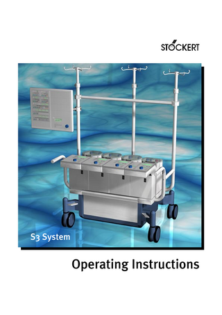
S3 System
Operating Instructions
S3 System • Operating Instructions Copyright © 2005 SORIN GROUP DEUTSCHLAND GMBH Lindberghstrasse 25 D-80939 München, Germany phone: fax:
+49 - 89 - 32301-0 +49 - 89 - 32301-555
All rights reserved. No part of this manual may be reproduced or copied in any form or by any means - be it graphic, electronic or mechanical, including photocopying, typing, or information and retrieval systems - without written permission of SORIN GROUP DEUTSCHLAND GMBH.
Operating Instructions Version 02/2005 - GA–5311–0005.05 E Valid for the S3 System operated with firmware version V1.xx and V2.xx
GA–5311–0005.05 E
S3 System • Table of Contents
Table of Contents 1
Introduction 1.1
2
3
About these operating instructions...1.1 1.1.1 Symbols used in these operating instructions ...1.1 1.1.2 The chapters in these operating instructions ...1.2 1.1.3 Glossary of terms and abbreviations ...1.3 1.1.4 Unit conversions ...1.4
Safety 2.1
Approvals ... 2.1
2.2
Regulations and safety instructions ... 2.2 2.2.1 Usage in accordance with regulations ... 2.2 2.2.2 General safety instructions ... 2.3 2.2.3 Operational safety ... 2.4 2.2.4 Electrical safety ... 2.4 2.2.5 Safety instructions for routine maintenance ... 2.5
2.3
Safety features of the S3 System ... 2.5
System description 3.1
General description of the S3 System ... 3.1 3.1.1 Components ... 3.1
3.2
Structure of the S3 System ... 3.2 3.2.1 Complete overview ... 3.2 3.2.2 Overview - control panel ... 3.4 3.2.3 Overview - pump control panels ... 3.6 3.2.4 Overview - electronics/power pack... 3.8 The components of the power supply ... 3.8 The components for monitoring and controlling ... 3.10 3.2.5 Overview - pumps... 3.11
GA–5311–0005.05 E
1
S3 System • Table of Contents
4
5
2
Installation 4.1
Preparing the installation... 4.1 4.1.1 General and technical requirements ... 4.1 4.1.2 Technical requirements for operation ... 4.1 Electrical connections ... 4.1
4.2
Performing the installation ... 4.2 4.2.1 Maximum scope of delivery ... 4.2 4.2.2 Assembling the S3 System... 4.3 Check list: assembly material and tools... 4.3 Assembling the mast system ... 4.4 Mounting the pumps ... 4.6 Mounting the control panel and the sensors... 4.7 Mounting the control modules... 4.8 Cable holding system ... 4.9 Holders with fast clamp connectors ... 4.10 4.2.3 Mounting the S3 mast pump extension unit ... 4.11 Positioning of the cables at the S3 mast pump ... 4.14 Connecting the S3 mast pump ... 4.15 Positioning of the cables at the mast pump extension unit... 4.16 Transportation of the S3 System ... 4.16 4.2.4 Mounting the sensors and components... 4.17 Bubble sensor... 4.17 Holder for the pressure transducer (optional)... 4.17 Blocking ferrites ... 4.18 Placing of the tubings at the S3 mast pump extension unit ... 4.19 Level sensor... 4.20 4.2.5 Connecting devices... 4.21 4.2.6 Connecting the sensors ... 4.22 4.2.7 Power supply for external devices ... 4.23 Connecting external devices to the S3 System... 4.23 Connecting the S3 System ... 4.25 4.2.8 Supplementary measures during initial installation... 4.26
Operation 5.1
Overview: operating the S3 System... 5.1 5.1.1 One-time and recurring measures... 5.1 5.1.2 Measures occurring at each operation... 5.1 Preoperative measures... 5.1 Measures during operation... 5.2 After the operation ... 5.2
5.2
Preparing for operation ... 5.3 5.2.1 Prior to powering up the S3 System... 5.3 Check list: check prior to powering up ... 5.3 5.2.2 Powering up the S3 System ... 5.4 Switching on the control panel ... 5.4 Self-test ... 5.5 Status messages of the system ... 5.6 Switching on the control modules ... 5.7 Switching off the control modules ... 5.7 Powering down the S3 System ... 5.7 Check list: check after powering up ... 5.8
GA–5311–0005.05 E
S3 System • Table of Contents
5.2.3 Preparing the uninterruptible power supply (UPS)... 5.10 Charging the accumulators ... 5.11 UPS menu ... 5.12 Checking the capacity of the accumulators... 5.13 Checking the accumulators (battery test) ... 5.14 5.3
General operation of the control panel... 5.17 5.3.1 Keys and symbols on the control panel... 5.20 General keys and symbols ... 5.20 Keys and symbols on the bubble detector ... 5.21 Keys and symbols on the level control ... 5.21 Keys and symbols on the pressure control... 5.22 Keys and symbols on the cardioplegia control... 5.22 Keys and symbols on the timers ... 5.23 Keys and symbols on the temperature monitor ... 5.23 Keys and symbols on the pulsatile flow control (PFC) ... 5.23 Keys and symbols on the multi data display module (MDM)... 5.24 The control elements and symbols on the central display module (CDM) ... 5.24 5.3.2 Selecting menus ... 5.25 5.3.3 Setting the parameters ... 5.27 5.3.4 Basic settings on the control panel (the system menus) ... 5.29 Changing the time and the push-button volume ... 5.29 Changing the date ... 5.30 Changing the display/alarm/language ... 5.31
5.4
Pump control... 5.32 5.4.1 Special safety instructions: pump control... 5.32 To your kind attention: ... 5.32 Check prior to each operation:... 5.33 Safety features of the pumps... 5.33 5.4.2 Control elements and symbols on the pump control panel ... 5.34 5.4.3 The control menu... 5.38 5.4.4 The basic settings menu ... 5.40 Switching on the pumps and calling up the basic settings menu ... 5.40 5.4.5 The pump menu... 5.41 Switching on the pump and calling up the pump menu ... 5.41 Changing the pump parameters... 5.42 Pump parameters: tube size ... 5.42 Pump parameters: fine calibration... 5.43 Pump parameters: assigning “master/slave” mode ... 5.46 5.4.6 Basic functions of the pump ... 5.48 Switching on and starting the pump ... 5.48 Stopping the pump ... 5.50 5.4.7 Control functions: control and alarm... 5.51 Displays of the control/monitoring status ... 5.52 Override of the control functions ... 5.55 5.4.8 Error messages of the pumps ... 5.57
GA–5311–0005.05 E
3
S3 System • Table of Contents
5.5
4
Working with the control panel... 5.58 5.5.1 The bubble detector ... 5.58 Configuring the bubble detector ... 5.59 Bubble detector: displays... 5.62 Bubble detector: alarm ... 5.63 5.5.2 Level control ... 5.66 Configuring the level control... 5.67 Level control: selecting the operating mode ... 5.70 Level control: displays ... 5.71 Level control: alarm ... 5.73 5.5.3 Pressure control... 5.76 Configuring the pressure control ... 5.77 Pressure control: selecting the operating mode ... 5.79 Pressure control: additional settings ... 5.81 Pressure control: displays ... 5.83 Pressure control: alarm ... 5.85 5.5.4 Cardioplegia control ... 5.88 Powering up/down the cardioplegia control... 5.90 Cardioplegia menu 1: basic configuration ... 5.91 Cardioplegia menu 2: second pump and pressure control ... 5.102 Cardioplegia and pressure control... 5.104 Working with the cardioplegia control ... 5.108 Cardioplegia control: displays ... 5.112 Cardioplegia control: alarm ... 5.115 5.5.5 Timer ... 5.120 Switching on the timer... 5.121 Configuring the timer... 5.122 Working with timers... 5.123 Timer: displays ... 5.123 5.5.6 Temperature monitor ... 5.124 Switching on the temperature monitor ... 5.125 Configuring the temperature monitor ... 5.126 Temperature monitor: displays... 5.128 Temperature monitor: alarm... 5.129 5.5.7 Pulsatile flow control (PFC) ... 5.130 Switching on the pulsatile flow control ... 5.131 Configuring the pulsatile flow control ... 5.132 Additional information about pulsatile operation ... 5.135 Working with the pulsatile flow control ... 5.137 Pulsatile flow control: displays ... 5.139 Pulsatile flow control: alarm ... 5.141 Alarm ... 5.141 5.5.8 Multi data display module (MDM) ... 5.142 Switching on the multi data display module ... 5.143 Configuring the multi data display module ... 5.143
GA–5311–0005.05 E
S3 System • Table of Contents
5.6
Assembling the S3 System... 5.146 5.6.1 Sensors ... 5.146 Bubble sensor: operating conditions ... 5.146 Bubble sensor: inserting the tubing... 5.147 Level sensor: operating conditions ... 5.148 Mounting the level sensor ... 5.148 Pressure sensors: operating conditions... 5.149 Mounting the pressure sensors ... 5.149 Check list: electrical connections... 5.150 5.6.2 Pumps: preparation ... 5.151 Turning the pump head ... 5.152 Inserting the tubing (tubing clamp block “Standard” ) ... 5.153 Blood cardioplegia (BCD) inserts (tubing clamp block “Standard”) ... 5.155 Insert the tubing (tubing clamp module “Variolock”)... 5.157 Blood cardioplegia (BCD) inserts (tubing clamp module “Variolock”) ... 5.160 Check list: pumps ... 5.162 5.6.3 Connecting the tubing set and the accessories... 5.163
5.7
Settings and system check ... 5.164 5.7.1 Basic settings ... 5.164 5.7.2 Adjustment of the pump occlusion ... 5.164 Method 1: adjusting the occlusion via pressure measurement ... 5.165 Method 2: adjusting the occlusion by means of a water column... 5.166 5.7.3 Measuring the flow rate ... 5.168 Arranging the measurement ... 5.169 Settings on the control panel... 5.170 Performing the measurement ... 5.171 5.7.4 Calibration of the pressure control... 5.172 Preparing the calibration ... 5.172 Performing the calibration ... 5.173 5.7.5 Configuring the S3 alarm amplifier ... 5.174 5.7.6 System check prior to operation: the overall system ... 5.176 Checks prior to powering up the system ... 5.176 Function check when powering up the system... 5.176 Checks after powering up the system ... 5.177 5.7.7 System check prior to operation: control/monitoring and alarm functions ... 5.178 Function test: bubble detector... 5.178 Function test: level control ... 5.180 Function test: pressure control ... 5.181 Function test: temperature monitor ... 5.183 Function test: pulsatile flow control... 5.184
5.8
Operating modes in emergencies ... 5.186 5.8.1 Power failure: UPS operation ... 5.187 Maximum duration for UPS operation... 5.187 Starting in case of an error in the power supply module ... 5.188 Starting without mains power... 5.189 Starting in case of a failure of the automatic accumulator switch ... 5.191 Power failure during operation ... 5.194 5.8.2 Operating the system manually (hand cranking)... 5.196
GA–5311–0005.05 E
5
S3 System • Table of Contents
6
7
6
Faults and errors 6.1
Avoidable causes for errors... 6.1 6.1.1 Mistakes in equipping the system ... 6.1 Sensors: sources of errors ... 6.1 Mistakes in mounting the disposables ... 6.2 Mistakes in configuring the system ... 6.2 6.1.2 Errors during operation... 6.3 6.1.3 Mistakes in maintenance and care... 6.4
6.2
Messages on the control panel ... 6.5 6.2.1 System status messages ... 6.5 Lost basic settings ... 6.5 UPS messages ... 6.6 UPS errors ... 6.7 Other errors: “E-codes” and “Sens” errors on the control panel... 6.8 Disconnecting the pump from a defective monitoring device... 6.10
6.3
Error messages on the pump control panel ... 6.12
6.4
Errors in the E/P pack... 6.16 Surge current protection... 6.16 Fuses ... 6.17
6.5
Errors in the UPS ... 6.19 Start during failure of automatic UPS activation ... 6.19
6.6
Errors in the sensor modules ... 6.21 Failure of an individual sensor module ... 6.22 Failure of all sensor modules ... 6.22
6.7
Other errors... 6.24
Routine maintenance 7.1
General maintenance instructions... 7.1 7.1.1 Safety instructions for routine maintenance ... 7.1 7.1.2 Regular maintenance checks by authorised service technicians... 7.2 7.1.3 Disposal in accordance with environmental regulations ... 7.3
7.2
Cleaning and disinfecting ... 7.4 7.2.1 Housing and pumps... 7.4 7.2.2 Accessories... 7.6 Cleaning and checking the bubble sensor... 7.6 Cleaning and checking the level sensor ... 7.7 Cleaning and checking the pressure transducer ... 7.7 Cleaning and checking the temperature probes... 7.8 Cleaning and checking the tubing clamp module “Variolock”... 7.9
7.3
Safety checks and functional checks... 7.10 7.3.1 Visual checks ... 7.10 7.3.2 Functional checks ... 7.12 Self-test during power-up and UPS status ... 7.12 Device-specific functional checks ... 7.12
GA–5311–0005.05 E
S3 System • Table of Contents
7.4
8
Check lists: maintenance intervals... 7.13 7.4.1 Maintenance of the components ... 7.13 Check list: daily and/or single usage ... 7.13 Check list: additional maintenance intervals ... 7.14
Appendix 8.1
S3 system specifications... 8.1 8.1.1 Dimensions, weights, operating conditions ... 8.1 S3 System (console) ... 8.1 S3 SlimLine (console) ... 8.2 Masts S3 System ... 8.3 Masts S3 SlimLine ... 8.3 Pumps ... 8.4 Control panel ... 8.4 8.1.2 Electrical specifications ... 8.5 E/P pack ... 8.5 UPS and accumulators... 8.5 Control panel ... 8.6 8.1.3 Modules and sensors... 8.8 Sensor module - level control/bubble detector ... 8.8 Sensor module - pressure control... 8.8 Pressure transducer... 8.8 Sensor module - cardioplegia ... 8.9 Sensor module - temperature monitor... 8.10 S3 - DC/DC module ... 8.10 8.1.4 Pumps ... 8.11
8.2
Labelling ... 8.12
8.3
Part numbers ... 8.13 8.3.1 S3 System... 8.13 8.3.2 S3 SlimLine... 8.17 8.3.3 System accessories ... 8.17
8.4
Warranty ... 8.20 8.4.1 Warranty ... 8.20 8.4.2 Exclusivity... 8.20 8.4.3 Requirements to give notice of defects ... 8.20 8.4.4 Warranty conditions... 8.21 8.4.5 Warranty restrictions ... 8.21 8.4.6 Exclusions from warranty... 8.22 8.4.7 Warranty claims ... 8.22 8.4.8 Transferability... 8.22 8.4.9 Choice of law ... 8.22
8.5
Disposables and accessories ... 8.23
8.6
Index... 8.25
GA–5311–0005.05 E
7
S3 System • Table of Contents
A1
8
Approvals and certificates A1.1
EC Certificate
A1.2
Quality management
A1.3
Information about electromagnetic compatibility (EMC)
GA–5311–0005.05 E
S3 System • Introduction
1
Introduction
1.1
About these operating instructions These operating instructions are the basis for the correct usage, operation and maintenance of the Stöckert S3 System. Although the System was designed to be easily understandable and intuitively operable, familiarity with this manual is an absolute prerequisite for the safe and efficient operation of the S3 System. Therefore, in the interest of the safety of both, the patient and the operator:
!
Read these operating instructions thoroughly before using the S3 System for the first time! These operating instructions provide valuable information even for the experienced user. Apart from purely describing operational steps they also contain information on how to avoid dangerous situations and errors. Moreover, they contain instructions for quick troubleshooting.
1.1.1
Symbols used in these operating instructions The symbols are intended to help the user find special text passages. The meaning of the symbols is as follows:
!
Danger! Failure to pay attention may cause danger to the patient’s and/or the operator’s life and health.
!
Warning! Failure to pay attention may cause damage to the machine or other equipment.
✓
A check list for a quick and safe follow up on whether operational steps have been carried out completely.
●
Primary list (main groups)
➜
Secondary list (subgroups)
GA–5311–0005.05 E
1.1
S3 System • Introduction
In addition, the following symbols are used in chapter 5 in order to differentiate between the location of the various texts in the menus: The menu shown is indicated on the display of the control panel.
The pump menu shown is indicated on the display of the corresponding pump control panel.
Where the menu text is not assigned a symbol, it is shown on the last marked display.
1.1.2
1.2
The chapters in these operating instructions In chapter...
you will find the following information:
1
Introduction
➜ Symbols used in these operating instructions ➜ Overview on chapters (this table) ➜ Glossary ➜ Unit conversions
2
Safety
➜ Important safety instructions for operation and maintenance of the S3 System
3
System description
➜ Description of all components
4
Installation
➜ Initial installation ➜ Preparing operation
5
Operation
➜ Setting up the S3 System ➜ Initial operation ➜ Function tests ➜ Operating all components
6
Faults and errors
➜ Instructions for troubleshooting
7
Routine maintenance
➜ User instructions for maintenance and care (no service instructions)
8
Appendix
➜ Specifications of all components ➜ Labelling ➜ Part numbers ➜ Warranty ➜ Index
A
Appendix (A1)
➜ Approvals and certificates
GA–5311–0005.05 E
S3 System • Introduction
1.1.3
Glossary of terms and abbreviations ● S3 System
➜ Stöckert S3 System, the heart-lung machine
● S3 System SlimLine
➜ Stöckert S3 System SlimLine, (smaller model of the S3 System: see chapter 8.1.1 “Dimensions, weights, operating conditions”)
● Control panel
➜ The mast-mounted control panel serves to centrally manage the control and monitoring functions of the S3 System. It contains the central display module (CDM) and either 6 or 10 slots for the individual control modules (or blank panels, depending on user’s system).
● Central display module (CDM)
➜ The central display module is mounted in the lower right corner of the control panel. It is the user interface for configuring the system and making assignments between components.
● Pump control panel
➜ The pump control panel is located on the upper side of the pump housing, proximal to the user. It contains the individual control elements and displays for its respective pump(s).
● Electronics and power pack (E/P pack)
➜ The electronics and power pack is located in the console base. It consists of the system power supply components (including the UPS), the pump connection strip and the sensor modules present in the system. All connection points for the pumps, control panel and connectable external equipment, the circuit breakers or fuses and control elements (e.g. the mains power switch) are accessible by opening the front flap of the console base. The sensor modules in the system are controlled and configured via the control panel.
● Sensor box
➜ The sensor module slots are located along the lower half of the front side of the E/P pack. There are nine slots available for the sensor modules of the various functional groups ( level/bubble, pressure, etc.). Non-used slots are covered with a blank cover plate.
● Control mode
➜ The pump is in control mode if a control and monitoring device is assigned to that pump.
GA–5311–0005.05 E
1.3
S3 System • Introduction
1.1.4
● Alarm (see “Control functions: control and alarm” on page 5.51)
➜ The pump stops if the assigned control device recognizes an alarm situation.
● Regulating mode (see “Control functions: control and alarm” on page 5.51)
➜ A control and monitoring device (either level control or pressure control) takes over control of the pump speed. The pump speed is decreased or allowed to accelerate to the set speed value, depending on the monitored conditions.
● HLM
➜ Heart-Lung Machine
● UPS
➜ Uninterruptible Power Supply
● O.R.
➜ Operating Room
● DMS
➜ Data Management System
● CAN
➜ Controller Area Network (CAN-Bus)
● IDDD or I3D
➜ Interface Digital/Digital/Digital
● MDM
➜ Multidata Display Module
● RP
➜ Roller Pump
● DHP
➜ Double Head Pump
● RPM
➜ Revolutions Per Minute
● LPM
➜ Litres Per Minute
● LED
➜ Light Emitting Diode
● LCD
➜ Liquid Crystal Display
● BCD
➜ Blood Cardioplegia Delivery
● PFC
➜ Pulsatile Flow Control
● PULS
➜ Pulsatile
● CONT
➜ Continuous (non-pulsatile)
● ECG
➜ Electrocardiogram
● BPM
➜ Beats Per Minute
● ID Label
➜ Identification Label
Unit conversions English standard ➜ metric 1 lb = 454 g
1 kg = 2.205 lbs
1 in = 25.4 mm
1 mm = 0.039 in
1 psi = 0.069 bar
1 bar = 14.5 psi
1 psi = 51.715 mmHg ( °F – 32 ) °C = ------------------------1.8
1.4
Metric ➜ English standard
1 mmHg = 0.019 psi °F = ( °C × 1.8 ) + 32
GA–5311–0005.05 E
S3 System • Safety
2
Safety
2.1
Approvals The S3 System has been designed to meet the following standards and regulations:
● IEC 601-1
–
Medical Electrical Equipment: General Requirements for Safety
–
EMC (Electromagnetic Compatibility)
● VBG
–
Regulations for the Prevention of Accidents
● MDD
–
Medical Device Directive (EC Directive 93/42 EEC of June 14, 1993)
● DIN EN ISO 13485
–
Quality Assurance
–
CE-Label
● IEC 601-1-2:1993 ● IEC 601-1-2:2001
The S3 System is a medical product, class IIb (EC Directive 93/42). A Declaration of Conformity has been issued for the S3 System. The present operating instructions are valid for S3 Systems developed to meet both, the requirements of IEC 601-1-2:1993 and IEC 601-1-2:2001.
GA–5311–0005.05 E
2.1
S3 System • Safety
2.2
Regulations and safety instructions
2.2.1
Usage in accordance with regulations ● In accordance with the applicable regulations, the Stöckert S3 System is used to perform, control and monitor extracorporeal circulation during cardiopulmonary perfusion. Any use beyond this specification is not in accordance with the regulations and SORIN GROUP DEUTSCHLAND GMBH will not assume any liability for damage in such a case. Usage in accordance with regulations also includes compliance with the operating instructions, as well as repair and maintenance according to the maintenance instructions. ● Relevant accident prevention measures according to existing local policy and employees’ health and safety regulations must be complied with. SORIN GROUP DEUTSCHLAND GMBH will not accept any liability for damage due to non-compliance with these regulations. ● SORIN GROUP DEUTSCHLAND GMBH will not assume any liability for injuries and/or damage caused by failure to observe the safety instructions or by the operator not taking due care. This also applies if the operator’s duty to take due care has not been specifically expressed to the user.
2.2
GA–5311–0005.05 E
!
S3 System • Safety
2.2.2
General safety instructions ● The Stöckert S3 System has been designed according to current state-of-the-art technology and accepted safety standards. Although this is the case, danger may arise for the patient, the user or for other equipment during operation. ● The S3 System must be operated and maintained by trained and qualified personnel only. ● The S3 System may only be used when the equipment is in good technical running order and, when used , in accordance with the applicable regulations and the operating instructions. Be sure to take note of cautions and warnings.
Usage in accordance with regulations: See chap. 2.2.1 on page 2.2
● The operating instructions must be available close to the machine at all times. Incomplete or illegible operating instructions must be replaced immediately. ● According to the European Directive 93/42 and the national standards based on this directive, the S3 System must be subjected to a regular maintenance check by an authorised service technician. The maintenance check must be performed after every 1000 operating hours or every 12 months, whichever comes first. ● In addition to the operating instructions, the relevant legal, general and binding regulations concerning the prevention of accidents must be observed. ● In order to take situations into account which are clinic-specific and outside of normal routine, e.g. certain working procedures, the operating instructions must be supplemented with relevant instructions (supervision and registration requirements, etc). ● Personnel operating the machine must have acquainted themselves thoroughly with the operating instructions prior to working on the machine! ● If modifications affecting safety or machine performance are noticed when the S3 System is not in use in the O.R., power it down immediately and have it checked by an authorised service technician.
Errors during operation in the O.R.: See chap. 6 on page 6.1
● Do not execute any modifications or extensions to the S3 System unless they have been tested and approved by SORIN GROUP DEUTSCHLAND GMBH, or else SORIN GROUP DEUTSCHLAND GMBH cannot assume any liability or responsibility. ● Keep the machine clean. This will prevent premature wear and faults due to dirt.
GA–5311–0005.05 E
Routine Maintenance: See chap. 7 on page 7.1
2.3
S3 System • Safety
2.2.3
Operational safety ● Prior to working with the S3 System, the user must have thoroughly read the operating instructions and have become familiar with the machine functions.
! !
● When in operation, the S3 System must be monitored at all times. Non-compliance with this duty may result in danger to the patient’s health. The safety features incorporated in the S3 System, e.g. visual and audible alarm signals, are intended to aid the operator, but do not exempt the operator from carefully monitoring the system during operation. ● The S3 System must not be used in the presence of explosive substances. ● Modifications or extensions to the machine, as well as the use of spare parts which have not been tested and approved by SORIN GROUP DEUTSCHLAND GMBH may have negative effects on the safety and function of the S3 System. SORIN GROUP DEUTSCHLAND GMBH cannot accept any liability or responsibility. ● Accessories and supplementary devices which have not been tested and approved by SORIN GROUP DEUTSCHLAND GMBH must prove that their use does not pose a safety hazard.
2.2.4
Electrical safety ● Electrical installations must be in accordance with the national standards and regulations. Please refer to the technical data.
Technical data: See “S3 system specifications” on page 8.1.
● The S3 System complies with the requirements for protection class 1 (IEC 601-1). It must be powered by a properly fused and grounded AC power supply. ● For safety reasons, you must connect the S3 System to a potential equalization point in the operating room (O.R.) using a potential equalization cable. ● Check the functional safety of all electrical connections, cables and sockets regularly.
Safety checks: See chap. 7.3 on page 7.10.
● External recording devices must comply with IEC 950.
2.4
GA–5311–0005.05 E
S3 System • Safety
2.2.5
Safety instructions for routine maintenance
!
● Disconnect the S3 System from the power supply prior to carrying out work involving routine maintenance. ● Do not fail to observe the regulations concerning routine maintenance, as well as the prescribed maintenance intervals stated in these operating instructions.
!
● Use recommended cleaning agents. ● Routine maintenance work must only be performed by qualified personnel. ● Repair work on the S3 System must only be carried out by authorised service personnel. Only original spare parts from SORIN GROUP DEUTSCHLAND GMBH must be used in order to guarantee the proper functioning of the system.
2.3
Safety features of the S3 System ● An emergency power supply (Uninterruptible Power Supply or UPS) is integrated into the S3 System, safeguarding an uninterrupted power supply in case of a power failure or other line disturbances.
Maximum time for UPS operation: See chap. 5.8 on page 5.186.
● In case of an emergency, the S3 System can be started via the UPS. ● During powering up, all pumps and devices integrated into the S3 System carry out an automatic self-test. ● Both, visual and acoustic alarms are triggered in case of a system error. ● Pumps which are connected to control and monitoring devices automatically slow down or stop in case of a fault.
Errors during operation in the O.R.: See chap. 6 on page 6.1.
● All pump errors occuring during operation are indicated on the corresponding pump control panel. Any other errors are indicated on the display of the control panel.
GA–5311–0005.05 E
2.5
S3 System • Safety
Notes:
2.6
GA–5311–0005.05 E