Instructions for Use
44 Pages
Preview
Page 1
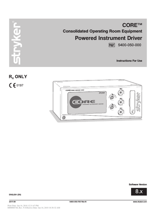
CORE™ Consolidated Operating Room Equipment
Powered Instrument Driver 5400-050-000
Instructions For Use
Software Version
8.x
ENGLISH (EN)
2017-09 Print Date: Jan 16, 2018 12:31:47 PM 0000004744, Rev. N Effective Date: Jan 16, 2018 10:38:32 AM
5400-050-700 Rev-N
www.stryker.com
Print Date: Jan 16, 2018 12:31:47 PM 0000004744, Rev. N Effective Date: Jan 16, 2018 10:38:32 AM
5400-050-700 Rev-N
EN
Table of Contents List of Illustrations ...4 Compliance Statements ...5 Software License Notice ...5 Limited Warranty ...5 Introduction ...6 Indications For Use ...6 Contraindications ...6 Safety Directives ...7 System Overview ...8 Hardware Features and Functions ...9 Accessories...9 Operating Instructions...10 To Connect the Components: ...10 Symbol Definitions ...10 Button Definitions: ...12 To Power Up: ...15 Software Menu Navigation ...16 To Select Settings: ...17 To Adjust Handpiece Speed (or Power): ...18 To Select Handpiece Mode and Direction: ...18 To Adjust Options: ...19 To Program Footswitch Options: ...20 To Set Handpiece Options: ...23 To Set Advanced Handpiece Options:...24 To Select a User Preference Favorite: ...25 To Replace a User Preference Favorite: ...25 To Adjust Irrigation Pump Settings: ...27 To Adjust the Console Options: - Standard and Advance User Mode...27 To Adjust Audio/Video Controls - Standard Mode ...27 To Access Advance User Mode...28 To Return to Standard User Mode...28 To Adjust the Console Options: - Advance User Mode ...29 To Select Console Language Preference - Advance User Mode Only...29 To Select Advance Console Settings - Advance User Mode Only ...29 To Select Network Connections - Advance User Mode Only ...30 To Manage User Preference Folders: - Advance User Mode Only...31 To Manage User Preference Files: - Advance User Mode Only ...31 To Manage User Preference Folders and Files: - Advance User Mode Only ...32 To Create a New Folder or File...32 To Modify a File ...33 To Add a Handpiece ...33 To View Settings ...34 To Edit Settings...34 To Edit Settings - Radio Frequency Identification (RFID) Handpiece and Cutters ...34 To Access System Information:...35 To Access Help: ...35 Cleaning and Disinfection ...36 Inspection, Testing, and Maintenance ...36 Troubleshooting...36 Storage and Handling ...37 Disposal/Recycle ...37 Messages ...37 Specifications ...39
www.stryker.com Print Date: Jan 16, 2018 12:31:47 PM 0000004744, Rev. N Effective Date: Jan 16, 2018 10:38:32 AM
3
EN
5400-050-700 Rev-N
List of Illustrations Figure 1. System Block Diagram ...8 Figure 2. Console Hardware Features and Functions...9 Figure 3. Console Interconnect Diagram ...10 Figure 4. Power Up Screen ...15 Figure 5. Plug In Handpiece Cable Screen ...15 Figure 6. Console Software Menu Map ...16 Figure 7. Home Screen - Overview ...17 Figure 8. Home Screen - Speed (or Power) ...18 Figure 9. Select Mode/Direction Screen ...18 Figure 10. Adjust Options Screen ...19 Figure 11. Footswitch Options Screens ...20 Figure 12. Assign Footswitch Screen - Automatic ...22 Figure 13. Assign Footswitch Screen - Manual ...22 Figure 14. Set Handpiece Options Screen ...23 Figure 15. Set Advanced Handpiece Options Screen...24 Figure 16. Select User Preference Favorite Pop-up ...25 Figure 17. Swap (replace) User Preference Favorite Pop-up...25 Figure 18. Select User Preference Favorite - Folder...26 Figure 19. Select User Preference Favorite - File ...26 Figure 20. Adjust Irrigation Pump Settings Screen...27 Figure 21. Adjust Console Options Screen - Standard User Mode ...27 Figure 22. Access Advance User Mode Pop-up ...28 Figure 23. Adjust Console Options Screen - Advanced User Mode ...28 Figure 24. Return to Standard User Mode Pop-up ...28 Figure 25. Select Language Preference Screen - Advance User Mode...29 Figure 26. Select Advance Console Settings Screen - Advance User Mode ...29 Figure 27. Select Network Connections Screen - Advance User Mode ...30 Figure 28. Manage User Preferences Screen - Folders ...31 Figure 29. Manage User Preferences Screen - Files ...31 Figure 30. Keyboard Screens...32 Figure 31. Modify File Screen ...33 Figure 32. Add Handpiece Screen ...33 Figure 33. View Handpiece Settings Screen ...34 Figure 34. Typical Edit Setting Screen ...34 Figure 35. System Information Screen ...35 Figure 36. Typical Help Screen ...35
4 Print Date: Jan 16, 2018 12:31:47 PM 0000004744, Rev. N Effective Date: Jan 16, 2018 10:38:32 AM
www.stryker.com
5400-050-700 Rev-N
EN
Compliance Statements Federal Communications Commission (FCC) FCC ID: Q9R-5400 This device complies with Part 15 of the FCC rules. Operation is subject to the following two conditions: (1) this device may not cause harmful interference, and (2) this device must accept any interference received, including interference that may cause undesired operation.
NOTE: FCC regulations provide that changes or modifications not expressly approved by Stryker Instruments could void your authority to operate this equipment.
Industry Canada (IC) IC: 4919A-5400 The term "IC:" before the radio certification number only signifies that Industry Canada technical specifications were met.
Software License Notice The Stryker CORE Powered Instrument Driver (console) contains software that is installed by the Stryker Corporation. Stryker Corporation owns this software; this software is never sold. Each sale of a software-containing product is not a sale of such software; it includes only a license to use the software in the product in which the software was initially installed. Stryker hereby grants you a nonexclusive, nontransferable License to use the software to operate the CORE Console for your own use and to perform maintenance on the CORE Console. You hereby agree that you will not copy, alter, modify, translate, disassemble, decompile, reverse engineer, create derivative works of, distribute, sub-license, sell, lease, lend, or otherwise transfer all or any portion of this software, in either original or modified form, except as specifically authorized under this License Agreement. In addition, you agree that you will not use this software in any product other than the Stryker product in which the software was initially installed by Stryker. EXCEPT FOR ANY WARRANTIES THAT MAY BE EXPRESSLY PROVIDED IN THE STRYKER PRODUCT LITERATURE ACCOMPANYING YOUR CORE CONSOLE OR SOFTWARE, THIS SOFTWARE AND DOCUMENTATION IS PROVIDED “AS IS,” AND STRYKER MAKES NO REPRESENTATIONS OR WARRANTIES, EXPRESS OR IMPLIED, INCLUDING BUT NOT LIMITED TO, WARRANTIES OF MERCHANTABILITY OR FITNESS FOR ANY PARTICULAR PURPOSE. STRYKER WILL NOT BE LIABLE FOR ANY INDIRECT, SPECIAL, PUNITIVE OR CONSEQUENTIAL DAMAGES ARISING OUT OF ANY USE OF THE SOFTWARE OR DOCUMENTATION. By using this software, you acknowledge and agree that you have read, understood, and agree to be bound by these terms and conditions.
Limited Warranty In the USA only, products of Stryker Instruments are warranted to the original purchaser for a period of one year from the date of purchase, with exceptions noted below. Products are warranted to be free from defects in material and workmanship. Abnormal wear and tear or damage caused by misuse or by failure to perform normal and routine maintenance as set out in the Maintenance Manual or Operating Instructions, or as demonstrated by an authorized Stryker Instruments representative, is not covered by the warranty. Any effort at field repair or adjustment may invalidate your warranty. Using any accessory that is not a Stryker product will invalidate your warranty. The warranty extends to all purchasers and is limited to the repair or replacement of the product without charge when returned prepaid to Stryker Instruments. There are no other expressed warranties. This warranty gives you specific legal rights and you may have other rights, which vary by state and municipality. For selected products. • Universal Handswitch is warranted for a period of 6 months from date of invoice. • Handpiece cords are warranted for a period of 6 months from date of invoice. • Cutting accessories are not warranted.
www.stryker.com Print Date: Jan 16, 2018 12:31:47 PM 0000004744, Rev. N Effective Date: Jan 16, 2018 10:38:32 AM
5
EN
5400-050-700 Rev-N
Introduction
Indications For Use
This instructions for use manual contains the information intended to ensure the safe, effective, and compliant use of your product. Keep and consult this reference manual during the life of the product.
The Stryker Consolidated Operating Room Equipment (CORE) System is intended for use in the cutting, drilling, reaming, decorticating, and smoothing of teeth, bone, cement, and other bone-related tissue in a variety of surgical procedures, including but not limited to spine, orthopedic, Neuro, ENT (Ear, Nose, and Throat), Dental, and Endoscopic. It is also usable in the placement or cutting of screws, metal, wires, pins, and other fixation devices.
Audience This manual is intended for in-service trainers, physicians, nurses, surgical technologists, and biomedical equipment technicians.
Conventions
Contraindications
The following conventions are used in this manual:
None known.
• A WARNING highlights a safety-related issue. ALWAYS comply with this information to prevent patient and/or healthcare staff injury. • A CAUTION highlights a product reliability issue. ALWAYS comply with this information to prevent product damage. • A NOTE supplements and/or clarifies procedural information.
Contact Information For additional information, including safety information, in-service training, or current literature, contact your Stryker sales representative or call Stryker customer service. Outside the US, contact your nearest Stryker subsidiary.
6 Print Date: Jan 16, 2018 12:31:47 PM 0000004744, Rev. N Effective Date: Jan 16, 2018 10:38:32 AM
www.stryker.com
5400-050-700 Rev-N
EN
Safety Directives WARNINGS: • Before using this equipment, or any component compatible with this equipment, read and understand the instructions for use. Pay particular attention to safety information. Become familiar with the equipment before use. • Only individuals trained and experienced in the use of this medical device should operate this equipment. Healthcare personnel should be thoroughly familiar with the instructions for use, handling characteristics, and the intended use(s) of this instrument. Contact your Stryker sales representative or Customer Service for in-service training. • The healthcare professional performing any procedure is responsible for determining the appropriateness of this equipment and the specific technique used for each patient. Stryker, as a manufacturer, does not recommend surgical procedure or technique. • Upon initial receipt and before each use, operate the equipment and inspect each component for damage. DO NOT use any equipment if damage is apparent or the inspection criteria are not met. See the Inspection, Testing, and Maintenance section for inspection criteria.
• All cutting accessories are intended for single use only. Reuse significantly increases wear on the handpiece and attachment. • All cutting accessories are intended for single use only. Reuse significantly increases wear on the handpiece and attachment. DO NOT reuse, reprocess, or repackage a device that is intended for single use only. - A single use device may not withstand chemical, chemical vapor, or high temperature sterilization reprocessing. - Design features may make cleaning difficult. - Reuse may create a contamination risk and compromise structural integrity resulting in operational failure. - Critical product information may be lost during repackaging. Failure to comply may lead to infection or cross infection and result in patient and/or healthcare staff injury. • ALWAYS use the appropriate accessory combination with a handpiece. Contact your Stryker sales representative for a complete list of accessories. • DO NOT attempt to insert or remove any cutting accessory or attachment while the handpiece is operating.
• Upon initial receipt and before each use, clean the equipment as indicated. See the Cleaning and Disinfection section for care information.
• DO NOT place a handpiece on a patient.
• DO NOT use this equipment in areas in which flammable anesthetics or flammable agents are mixed with air, oxygen or nitrous oxide.
• DO NOT place a handpiece on or near a magnetic pad or tray. A magnetic field can simulate the output of a handswitch or footswitch and may cause the handpiece to operate inadvertently.
• Take special precautions regarding electromagnetic compatibility (EMC) when using medical electrical equipment like the CORE console. Install and place the console into service according to the EMC information contained in this manual. Portable and mobile radio frequency (RF) communications equipment can affect the function of the CORE console. • To avoid the risk of electric shock, ALWAYS connect this equipment to a hospital-grade, facility power receptacle with protective earth. DO NOT modify the ground connection of the console power cord. • DO NOT stack or place equipment adjacent to the CORE console if possible. If such a configuration is necessary, carefully observe the configuration in question to ensure that electromagnetic interference does not degrade performance. • ALWAYS follow the recommended duty cycle to prevent the equipment from overheating. See the Specifications section and/or the instructions for use supplied with the handpiece. • ALWAYS operate the equipment within the specified environmental condition values. See the Specifications section.
• If power is lost, some of the console’s programmed settings, such as the handpiece to footswitch assignment, the footswitch options, and the handpiece operating modes, will revert to their original default configuration or the last selected User Preference configuration. After power is restored, reprogram the console settings as required. • Operating a handpiece in the Window Jog mode may increase the temperature of the handpiece. If a handpiece overheats, the console automatically shuts off the handpiece. Monitor the heat response in relation to the type of surgical procedure being performed. Frequently check the distal tip and body until you are familiar with its temperature rise characteristics. • Ensure the handpiece speed does not exceed the specified attachment limitations. • If operated for extended periods of time, a handpiece may exceed its nominal operating temperature range. A console warning message will appear when the nominal operating range is approached, and again when it is exceeded. Allow the handpiece to cool before restarting. • Use personal protective equipment (PPE).
www.stryker.com Print Date: Jan 16, 2018 12:31:47 PM 0000004744, Rev. N Effective Date: Jan 16, 2018 10:38:32 AM
7
EN
5400-050-700 Rev-N
System Overview The Stryker CORE Powered Instrument Driver (console) provides an integrated, centrally controlled environment that promotes safe and economical surgical practice. The console’s software provides control over system components including the console, the graphical user interface (GUI), the irrigation pump, and the connected handpieces and footswitches (see figure 1). The software’s file management capability allows you to save and store user preference settings and have convenient access to a favorites list of the most frequently used files to improve efficiency. The color display, with its touch sensitive screen, provides an intuitive graphical user interface that allows you to view multiple system components and set their parameters with the touch of a finger. Changes may be made rapidly, with little to no interruption during surgery. Multiple handpieces and footswitches may be connected and operated simultaneously from a single console. Because options vary among different handpieces, the console will only display those options that are related to the connected handpiece. An integral irrigation pump system reliably supplies coolant/irrigation to the cutting site with adjustable flow rates. Various cutting accessories and irrigation cassettes used with the system are also recognized and identified on the console screen by means of tag technology. Console settings, like display brightness and speaker volume, may be easily adjusted. The on board speaker provides audible feedback during operation and configuration. The console accepts either 100 VAC - 230 VAC input and has the capability to power heavy duty handpieces. The Stryker Firewire Backbone (SFB) serial connection provides a serial communications channel between the console and other devices. This feature allows software upgrades over a computer network.
Facility Power
SFB Serial Connection
Other Devices via Computer Network
Handpiece 1 Main Processor
Handpiece Control Handpiece 2
CORE Console
Handpiece 3
Footswitch 1 Footswitch and Irrigation Pump Control Footswitch 2 Touch Sensitive Screen
Finger/Stylus Input
Color Display
Speaker Irrigation Pump
Graphical/ Audio Output
Irrigation Pump Cassette
Figure 1. System Block Diagram
8 Print Date: Jan 16, 2018 12:31:47 PM 0000004744, Rev. N Effective Date: Jan 16, 2018 10:38:32 AM
www.stryker.com
5400-050-700 Rev-N
EN
Hardware Features and Functions The hardware feature and functions section provides the location and function of each major feature of the console and may be used during the interconnection of system components (see figure 2).
Color Touch Screen Display Area: Allows you to view and make handpiece settings using its touch screen capability.
Footswitch Connection Area: Allows you to connect two footswitches simultaneously.
Handpiece Connection Area: Allows you to connect three handpieces simultaneously.
Irrigation Pump Cassette: Install the irrigation cassette here if you use the irrigation pump (optional).
Power Switch: Press to turn console power ON and OFF.
Speaker: Provides audible sounds and alarms (located inside console). Irrigation Bag Pole Mounting Bracket: Connect the pole here if you use the irrigation pump (optional).
SFB Serial Connectors: Three communication ports allow you to transfer data and control information such as software upgrades.
Power Receptacle: Connect the console to facility power using the console power cord.
Figure 2. Console Hardware Features and Functions
Accessories WARNING: Use only Stryker-approved components and accessories, unless otherwise specified. Using other components and accessories may result in increased electromagnetic emissions or decreased electromagnetic immunity of the system. DO NOT modify any component or accessory without the authorization of the manufacturer. NOTE: For a complete list of accessories, contact your Stryker sales representative or call Stryker customer service. Outside the US, contact your nearest Stryker subsidiary. The following Stryker-approved accessories are sold separately: Description
REF
Power Cord ... 0996-851-010; 0590-100-002 Cable; push-pull type connector with alignment markings and keyed connectors ...5100-004-000 TPS™ Unidirectional Footswitch ... 5100-007-000 TPS Footswitch ...5100-008-000 Irrigation Pole ...5100-050-028 NSE Footswitch...5400-007-000 Disposable Irrigation Cassette ... 5400-050-001 Dual Disposable Irrigation Cassette ... 5400-050-002 The Mill Cable...5400-704-000 Electric System 6 Handpiece Cord... 6292-004-000
www.stryker.com Print Date: Jan 16, 2018 12:31:47 PM 0000004744, Rev. N Effective Date: Jan 16, 2018 10:38:32 AM
9
EN
5400-050-700 Rev-N
Operating Instructions To Connect the Components: The console interconnect diagram provides the connection sequence of system components. The numbered call outs correspond to the numbered instructions on the next page. See the instructions for use supplied with each component for specific connection information. The illustrated hardware below provides a likeness, but may not be an exact representation of the actual hardware (see figure 3).
Figure 3. Console Interconnect Diagram
Symbol Definitions The symbols located on the equipment and/or labeling are defined in this section and/or in the Symbol Definition Chart. See the Symbol Definition Chart supplied with the equipment. SYMBOL
DEFINITION
SYMBOL
DEFINITION
SYMBOL
DEFINITION
On/Off (push-push)
Type BF Applied Part
Equipotential
Footswitch
SFB Serial Connection
General warning sign
Handpiece
Alternating Current
Refer to instruction manual/ booklet
Irrigation
Direct Current
Non-ionizing electromagnetic radiation
10 Print Date: Jan 16, 2018 12:31:47 PM 0000004744, Rev. N Effective Date: Jan 16, 2018 10:38:32 AM
www.stryker.com
5400-050-700 Rev-N
EN
To Connect the Components (continued): NOTE: See figures 2 and 3 while performing the instructions below. See the instructions for use supplied with each component for specific connection information. 1. Place the console on a sturdy, flat surface near a hospital-grade outlet. 2. Install the power cord plug into the power receptacle on the console. 3. Install the other end of the power cord into a hospital-grade wall outlet. 4. Press the power switch to turn the console on. See To Power Up and To Adjust Options sections for more information.
NOTES: • The universal power supply will automatically adjust to match the voltage and frequency of the facility power. • As you connect components to the console, the console’s screen will change to display the specific components that are connected.
CAUTIONS: • DO NOT thread or twist the push/pull connectors on the cords during installation or removal. • When connecting or disconnecting a cable(s) to the front of the console, always hold the cable by its connector (the plug, not the cord). Failure to comply may result in damage to the cable or console. • Cables that are connected to the front of the console have keyed, push-pull type connectors that lock into place. DO NOT force a connector into a console port. Each connector and port has an alignment mark to indicate proper cable orientation. 5. If using a footswitch, plug the footswitch cable into the console port marked with a FOOTSWITCH PORT symbol. Align the marks and gently push the connectors together. Two footswitches may be connected to the console.
NOTE: A registered wireless footswitch will be overridden and disabled when a wired footswitch is connected and registered to the same color footswitch port. 6. Plug the handpiece cord(s) into the console port(s) marked with a HANDPIECE PORT symbol. Align the marks and gently push the connectors together. Three handpieces may be connected to the console and two handpieces may be operated simultaneously.
NOTES: • If using a CORE Universal Handswitch, attach it to the handpiece before you plug the cord into the handpiece. • If using CORE console software version 6.1 or later, a Heavy Duty Power Pack (power pack) may be used to allow either a Stryker System 4 or 5 Heavy Duty Handpiece to operate with the console. If a power pack is connected to the console, the associated heavy duty handpiece will take priority over other attached, inactive handpieces. Only one heavy duty handpiece may be operated using the power pack with the console. No other connected handpieces will be allowed to operate. See instructions for use supplied with the Heavy Duty Power Pack for connection information. 7. Plug the other end of the handpiece cord(s) into the handpiece(s). See instructions for use supplied with each handpiece for connection information.
WARNING: Use only Stryker approved cutting accessories. 8. Attach the cutting accessory to the handpieces. See the instructions for use supplied with each handpiece or attachment for cutting accessory installation information.
NOTE: If using the console irrigation pump (optional), install the Irrigation Pole REF 5100-050-028 (optional; may use equivalent irrigation pole) to the mounting bracket on the back of the console. Hang the irrigation bag from the pole. 9. If required, install the irrigation cassette into the console port marked with a IRRIGATION PUMP CASSETTE symbol. 10. If required, connect the irrigation tubing to the irrigation bag. 11. If required, attach the irrigation sleeve/clip to the handpiece(s) and connect the tubing. Connect the irrigation tubing to the handpiece. See the instructions for use supplied with each handpiece for connection information. 12. Test all the system components to ensure that they are performing properly before surgery. Refer to the Button Definitions and Software Menu Navigation sections when using the graphical user interface.
www.stryker.com Print Date: Jan 16, 2018 12:31:47 PM 0000004744, Rev. N Effective Date: Jan 16, 2018 10:38:32 AM
11
EN
5400-050-700 Rev-N
Button Definitions: The button definitions section provides a complete list of the buttons as they appear on screens within the software interface. BUTTON
NAME
DEFINITIONS
NAME
DEFINITIONS
HOME
Access the HOME screen to view and adjust handpieces and system settings
BUTTON
OSCILLATE (OSC)
Set default mode of handpiece to oscillate
HELP
Access task-oriented HELP related to screen and button functionality
FORWARD (FWD)
Set default mode of handpiece to rotate in the Forward (clockwise) direction
BACK
Return to the previous screen
REVERSE (REV) Set default mode of handpiece to rotate in the Reverse (counterclockwise) direction
UP
Scroll up
LOW
Set default mode of handpiece to operate in the low RPM range mode
INCREASE
Increase the value of a setting
HIGH
Set default mode of handpiece to operate in the high RPM range mode
DOWN
Scroll down
ADJUST OPTIONS
Adjust handpiece and footswitch options
DECREASE
Decrease the value of a setting
FIXED SPEED
Set the default run mode of the handpiece speed to operate at the set speed only
OK
Accept inputs, changes or selections and return to previous screen
VARIABLE SPEED
Set the default run mode of the handpiece speed to respond to the degree of pressure applied to the handswitch or footswitch
ESCAPE (ESC)
Close (Escape) a pop-up or screen without accepting inputs, changes or selections and return to previous screen
ONE TOUCH
Set the default run mode of the handpiece activation to respond to one touch of a handswitch or footswitch
FACTORY DEFAULT
Apply original factory default settings
PROGRAM FOOTSWITCH
Program the footswitch pedals and pads based on the handpiece capabilities
DISABLE BUTTONS
Disable all four NSE Footswitch pads
ASSIGN FOOTSWITCH TO HANDPIECE
Assign a specific footswitch port to a specific handpiece port
Toggle between the NSE Footswitch Options SWITCH FOOTSWITCH screen and the TPS Footswitch Options screen
12 Print Date: Jan 16, 2018 12:31:47 PM 0000004744, Rev. N Effective Date: Jan 16, 2018 10:38:32 AM
www.stryker.com
5400-050-700 Rev-N
EN
Button Definitions: (continued) BUTTON
NAME
DEFINITIONS
SET HANDPIECE OPTIONS
Select specific handpiece options and assign them to a particular handpiece button
NAME
DEFINITIONS
SAVE CURRENT SETTINGS
Save current console settings to the selected file in the user preference favorites list
Create and modify user preference MANAGE folders and files USER PREFERENCES
ADJUST CONSOLE OPTIONS
Adjust console options in the standard or advanced mode
DELETE
Delete a folder, file or handpiece from a user preference file
ADJUST VOLUME AND SCREEN
Adjust console volume, brightness and contrast
CREATE FILE
Create a new user preference file
SELECT LANGUAGE PREFERENCE
Select the language to be displayed on the console screen
COPY CURRENT SETTINGS
Copy the current active user preference settings to a new file
SELECT ADVANCED CONSOLE SETTINGS
Select network settings
CREATE FOLDER
Create a new user preference folder
ACCESS ADVANCED MODE
Access user preference options
OPEN AND MODIFY
Open a user preference folder and modify the file(s) as required
SELECT USER PREFERENCE FAVORITE
Select one of five favorite user preference files as the console default
NAVIGATE UP
Navigate up one directory
SWAP USER PREFERENCE FAVORITE
Replace one of the five favorite user preference files with another preference file
ACCESS HANDPIECE SCREEN
Access the Add Handpiece screen
ACCESS ADVANCED HANDPIECE OPTIONS
Access advanced handpiece options
ADD HANDPIECE
Add handpiece to a user preference file
SYSTEM INFORMATION
Access to System Information screen to view hardware and software information
VIEW/EDIT SETTINGS
View and edit the user preference file settings of a selected handpiece
ADJUST IRRIGATION PUMP SETTINGS
Adjust and apply an irrigation flow rate to a handpiece cutting accessory
EDIT SETTINGS
Change user preference file settings
www.stryker.com Print Date: Jan 16, 2018 12:31:47 PM 0000004744, Rev. N Effective Date: Jan 16, 2018 10:38:32 AM
BUTTON
13
EN
5400-050-700 Rev-N
Button Definitions: (continued) BUTTON
NAME
DEFINITIONS
FLUSH TUBING SET
Provide a continuous irrigation flow rate to flush the tubing set
AUTO PRIME TUBING SET
Prime the tubing set to the irrigation tip
SELECT NETWORK CONNECTIONS
Select specific network connections
Select English as console screen language
English
SELECT ENGLISH LANGUAGE
Select German as console screen language
Deutsch
SELECT GERMAN LANGUAGE
Select French as console screen language
Français
SELECT FRENCH LANGUAGE
Select Spanish as console screen language
Español
SELECT SPANISH LANGUAGE
Select Italian as console screen language
Italiano
SELECT ITALIAN LANGUAGE
14 Print Date: Jan 16, 2018 12:31:47 PM 0000004744, Rev. N Effective Date: Jan 16, 2018 10:38:32 AM
www.stryker.com
5400-050-700 Rev-N
EN
To Power Up: This screen is momentarily displayed while the console powers up. Note the software version is displayed in the lower right corner of the screen (see figure 4).
Powered Instrument Driver
XXXX-XXX-XXX X.X_build_X
Figure 4. Power Up Screen
If no handpieces or cords are connected to the console during initial power up, the following screen will appear (see figure 5):
Figure 5. Plug In Handpiece Cable Screen
www.stryker.com Print Date: Jan 16, 2018 12:31:47 PM 0000004744, Rev. N Effective Date: Jan 16, 2018 10:38:32 AM
15
EN
5400-050-700 Rev-N
Software Menu Navigation The software menu map is a visual representation of how the software is structured and is designed to facilitate navigation (see figure 6). The map also provides the sequence of screen information provided in this manual, top down and left to right. The icons used in this map are button icons used in the software and also reside near header information in this manual. The screen illustrations used in this manual provide a likeness, but may not be an exact representation of the actual console screens.
Home Screen
Adjust Speed/ Power
Adjust Options
Select Direction/Mode
Select User Preference Favorite
Adjust Irrigation Pump Settings
Swap User Preference Favorite
Adjust Audio Video Controls
Program Footswitch Options
Adjust Console Options
Access Help
Access System Information
Access Advance User Mode
Assign Footswitch
Create New Folder(s)
Manage User Preferences Folders
Select Console Language Preference
Set Handpiece Options
Create New File(s)
Manage User Preference Files
Access Advance Console Controls
Set Advanced Handpiece Options
Add Handpiece
Modify File
Select Network Connections
Edit Settings
Figure 6. Console Software Menu Map
16 Print Date: Jan 16, 2018 12:31:47 PM 0000004744, Rev. N Effective Date: Jan 16, 2018 10:38:32 AM
www.stryker.com
5400-050-700 Rev-N
EN
To Select Settings: WARNING: DO NOT touch the console screen with a tool or hard object. Failure to comply may damage the screen and result in patient injury. The HOME screen is where most user interaction will take place (see figure 7). Up to three handpieces may be displayed on the screen simultaneously. When the console is initially turned on, the console settings are factory default settings until a user preference file is selected or the settings are manually modified.
NOTE: If the console screen is touched in two places simultaneously, unintended button activation may result.
Handpiece Operating Area View and modify key handpiece settings.
SABER DRILL
Coring Tool
ACL
65000
View User Preference File Name View name of file that contains handpiece settings for a specific procedure, for example, ACL (Anterior Cruciate Ligament) surgery. Console Operating Area Access key console functions.
FORMULA HANDPIECE
1520 Attached Handpieces Three handpieces may be attached to the console and two may be operated simultaneously.
View Handpiece Name View name of active handpiece. Three handpieces may be connected and displayed. Two powered handpieces may be operated from the same console, simultaneously.
CORE HIGH TORQUE
40% SABER DRILL
Coring Tool
65000 View Option Settings View option settings such as irrigation, footswitch control, and fixed or variable RPM (revolutions per minute). All of these settings may be modified.
View Cutting Accessory or Attachment Name View cutting accessory or attachment name if the handpiece, accessory and/or attachment have been selected or have recognition capability.
Figure 7. Home Screen - Overview
www.stryker.com Print Date: Jan 16, 2018 12:31:47 PM 0000004744, Rev. N Effective Date: Jan 16, 2018 10:38:32 AM
17
EN
5400-050-700 Rev-N
To Adjust Handpiece Speed (or Power): From the HOME screen, touch the plus and minus buttons to adjust the handpiece speed or power set point in RPMs or percentage of power (see figure 8).
NOTE: When you install a cutting accessory with cutter recognition capability or select an attachment, the system will automatically override the selected speed setting in each mode to the speed settings that are appropriate for the installed cutting accessory.
While the handpiece is running, the display shows the actual handpiece speed. If the handpiece is not running, the default or selected speed is displayed. The default speed is displayed for each handpiece until you adjust the speed set point based on the handpiece capability or modify the speed in a user preference file.
SABER DRILL
Coring Tool
65000 FORMULA HANDPIECE
1520 CORE HIGH TORQUE
40% Touch the adjustment buttons (or slider bar that becomes visible when touching the speed value) to increase or decrease the speed (power) set point. Figure 8. Home Screen - Speed (or Power)
To Select Handpiece Mode and Direction: From the HOME screen, touch the Select Direction/Mode button to adjust the handpiece direction and mode (see figure 9).
NOTE: The available handpiece options, including handpiece direction and mode, will depend on the type of handpiece that is identified at the top of the screen. REVERSE: Touch to cause the handpiece cutting accessory to rotate in the reverse (counterclockwise) direction.
NOTE: Five audible beeps notify the user that the cutting accessory is rotating in the reverse (counterclockwise) direction.
Direction Options: Select the direction of the cutting accessory.
FORWARD: Touch to cause the handpiece cutting accessory to rotate in the forward (clockwise) direction.
Select mode/direction - FORMULA HANDPIECE
OSCILLATE: Touch to cause the handpiece cutting accessory to oscillate.
Direction
Mode Options: Select the mode of handpiece operation. Mode
HIGH: Touch to cause the handpiece to operate in the high RPM range mode.
LOW: Touch to cause the handpiece to operate in the low RPM range mode.
Figure 9. Select Mode/Direction Screen
18 Print Date: Jan 16, 2018 12:31:47 PM 0000004744, Rev. N Effective Date: Jan 16, 2018 10:38:32 AM
www.stryker.com
5400-050-700 Rev-N
EN
To Adjust Options: From the HOME screen, touch the Adjust Options button to adjust the handpiece options (buttons and trigger, such as handswitch). The available handpiece options will depend on the type of handpiece that is identified at the top of the screen (see figure 10).
NOTE: To program the footswitch pedals and pads, touch the Footswitch Options button.
Adjust Acceleration
Select Run Mode
• Touch the plus and minus buttons or slider bar to adjust the percent of acceleration [0 to 100%].
• FIXED: handpiece runs at the full set speed or power. Varying pressure on the handswitch (or trigger) will not vary the handpiece speed or power.
• At 100%, the handpiece speed accelerates quickly. Acceleration slows as the setting approaches zero percent.
• VARIABLE: handpiece speed responds to the degree of pressure applied to the handswitch (or trigger).
Adjust options - FORMULA HANDPIECE - 3rd Port
Accelerate
46 %
Brake
36 %
Osc Turns
10
• ONE TOUCH: Handpiece activation responds to one touch of a trigger device (handswitch) and continues to run when the trigger device is released. Handpiece is deactivated by touching any trigger device. In this mode, the handpiece operates at constant set-point speed/power level.
Adjust Braking
Adjust Oscillate Turns
• Touch the plus and minus buttons or slider bar to adjust the percent of braking [0 to 100%].
• Touch the plus and minus buttons to select the number of turns per direction when running a handpiece in the oscillate mode.
• At 100%, the handpiece stops abruptly. The amount of deceleration decreases as the setting approaches zero percent.
• Touch the minus button until the TIME-BASED icon is visible to operate in a TIME-BASED mode where the number of turns are based on the speed of the handpiece.
Figure 10. Adjust Options Screen
www.stryker.com Print Date: Jan 16, 2018 12:31:47 PM 0000004744, Rev. N Effective Date: Jan 16, 2018 10:38:32 AM
19
EN
5400-050-700 Rev-N
To Program Footswitch Options: From the Adjust Options screen, touch the Program Footswitch button to program the footswitch pedals and pads based on the capabilities of the connected handpiece (see figure 11). Two footswitches may be connected to and simultaneously operated from the same console. However, two footswitches cannot be used to control the same handpiece at the same time.
TPS Footswitch Options Screen
Foot-Switch Options - FORMULA HANDPIECE - 3rd Port Handpiece port
Change Port
OSC <> High/low
High <> Low
Direction: REV Op Mode: Default Run Mode: Var
Direction: FWD Op Mode: Default Run Mode: Var
III
Pedal A Options - FORMULA HANDPIECE - 3rd Port
Op Mode
Direction REV Op Mode
Default
Default
High Low OSC
Run Mode Var
NSE Footswitch Options Screen
Assign Specific Option Select a footswitch pad [I, II or III] or pedal [A, B or NSE Footswitch] and assign a specific option.
View Handpiece Port Indicates the assigned handpiece port for which the footswitch is programmed.
Touch the arrow buttons to scroll through the footswitch options. The available options are handpiece specific. Touch the OK button to select the option.
Disable
Fwd <> Rev
Irrigation on/off
Figure 11. Footswitch Options Screens
20 Print Date: Jan 16, 2018 12:31:47 PM 0000004744, Rev. N Effective Date: Jan 16, 2018 10:38:32 AM
www.stryker.com