Teleflex Medical
NextStep® Antegrade Chronic Hemodialysis Catheter
4 Pages
Preview
Page 1
NextStep® Antegrade Chronic Hemodialysis Catheter Rx only.
Product Description
7. Clinicians must be aware of potential entrapment of the guidewire by any implanted device in circulatory system. It is recommended that if patient has a circulatory system implant, catheter procedure be done under direct visualization to reduce risk of guidewire entrapment.
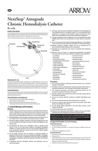
The Arrow® NextStep® Antegrade consists of a catheter with a dual lumen radiopaque polyurethane body, step-tip configuration, and 6 cm spacing between two ports. This catheter is first tunneled antegrade to venous insertion site, followed by vessel access and tip placement (refer to Figure 1).
8. Passage of guidewire into the right heart can cause dysrhythmias, right bundle branch block, and a perforation of vessel, atrial or ventricular wall.
The Arrow® NextStep® Antegrade Catheter is manufactured from radiopaque polyurethane.
Extension Lines Arterial Port
9. Do not use excessive force when introducing guidewire or tissue dilator as this can lead to vessel perforation, bleeding, or component damage.
Extension Line Clamps
Luer Connections
10. Patients requiring ventilator support are at an increased risk of pneumothorax during subclavian vein cannulation. 11. Extended use of subclavian vein may be associated with subclavian vein stenosis.
Juncture Hub
12. Clinicians must be aware of complications/undesirable side-effects associated with central venous catheters including, but not limited to: • laceration of vessel • air embolus • bacteremia • lumen thrombosis • brachial plexus injury • mediastinal injury • caval perforation w/bronchial • puncture/perforation of vessel communication • pleural injury • cardiac arrhythmia • pneumothorax • cardiac tamponade • retroperitoneal bleed • central venous thrombosis • right atrial puncture • endocarditis • septicemia • exit site infection • thoracic duct laceration • exsanguination • tunnel infection • femoral nerve damage • vascular thrombosis • hematoma • venous stenosis • hemorrhage • subcutaneous hematoma • hemothorax
Venous Port
Cuff
Figure 1
Indications for use: The Arrow NextStep Antegrade Catheter is indicated for use in attaining long-term vascular access for hemodialysis and apheresis. The Arrow NextStep Antegrade Catheter is inserted percutaneously and is preferentially placed into the internal jugular (IJ) vein. Alternately, this catheter may be inserted into the subclavian vein although the jugular vein is the preferred site. Catheters greater than 40 cm are intended for femoral vein insertion. The Arrow NextStep Antegrade Catheter is intended for use in adult patients.
Precautions:
Contraindications:
3. Use standard precautions and follow institutional policies for all procedures including safe disposal of devices.
1. Do not alter any kit/set component during insertions, use or removal (except as instructed). 2. Procedure must be performed by trained personnel well versed in anatomical landmarks, safe technique and potential complications.
The Arrow NextStep Antegrade Catheter is intended for long-term hemodialysis vascular access only and should not be used for any other purpose other than those indicated herein. Do not use this catheter in patients with thrombosed vessels.
4. Examine catheter and extension lines before and after each treatment for any signs of damage. 5. Do not use acetone with this catheter or catheter degradation may occur.
Clinical Benefits to be Expected: • • • •
Permits long term vascular access for hemodialysis and apheresis. Permits vascular access percutaneously. Permits vascular access by way of the internal jugular, subclavian veins. Catheters greater than 40 cm permit vascular access by way of the femoral veins.
6. Do not use sharp instruments near extension lines or catheter. 7. Do not use clamps other than those that are provided. Using other clamps may damage the catheter. 8. Do not clamp tubing repeatedly in the same place. Doing so may weaken the tubing.
General Warnings and Precautions Warnings:
9. Avoid clamping near Luer-Lock fittings.
1. Sterile, Single use: Do not reuse, reprocess or resterilize. Reuse of device creates a potential risk of serious injury and/or infection which may lead to death. Reprocessing of medical devices intended for single use only may result in degraded performance or a loss of functionality.
10. Repeated over tightening of bloodlines, syringes and caps will reduce connector life and could lead to potential connector failure. Kits/Sets may not contain all accessory components detailed in these instructions for use. Become familiar with instructions for individual component(s) before beginning the procedure.
2. Read all package insert warnings, precautions and instructions prior to use. Failure to do so may result in severe patient injury or death. 3. All chronic dialysis catheters should be used only as bridge devices and are not intended for extended use unless no other hemodialysis access options exist.
A Suggested Procedure: Use Sterile Technique. Prepare for Insertion:
4. Air embolism can occur if air is allowed to enter a vascular access device or vein. Do not leave open needles or uncapped, unclamped catheters in venous puncture site. Use only securely tightened LuerLock connections with any vascular access device to guard against inadvertent disconnection.
1. Identify appropriate vein for insertion. 2. Use direct visualization technologies, e.g., ultrasound or fluoroscopy, if available; and assess vein health. 3. Position patient as appropriate for insertion site.
Prep Puncture Site:
5. Do not apply excessive force in placing or removing catheter or guidewire. Excessive force can cause component damage or breakage. If damage is suspected or withdrawal cannot be easily accomplished, radiographic visualization should be obtained and further consultation requested.
1. Prep puncture site with appropriate antiseptic/agent. 2. Drape puncture site. 3. Identify appropriate venous insertion site and exit site by holding catheter in correct position over the patient’s chest. Appropriate catheter length is required to ensure that the catheter tip is within the right atrium to provide for optimal flow. 4. Administer local anesthetic per institutional policies and procedures.
6. If guidewire becomes damaged, catheter and guidewire must be removed together. 1
Recommended Antegrade Technique for New Insertion Sites
Exit Site Creation:
Refer to Arrow Simplicity® Micro-Introducer Set instructions if using micro-puncture technique.
1. Make a small incision no more than 6 cm lateral from venous insertion site to the desired exit site.
Flush Catheter:
2. Identify a point inferior and parallel beneath clavicle. This incision should be wide enough to accommodate the catheter cuff, approximately 5 mm in width.
1. Flush each lumen with sterile normal saline for injection to establish patency and prime lumen(s). 2. Clamp extension line(s) to contain saline within lumen(s).
Warning: There is an increased risk of catheter related infections with femoral vein insertion. To decrease this risk, create exit site in pelvic region.
Gain Initial Vessel Access:
3. Enlarge cutaneous puncture site with cutting edge of scalpel positioned away from the guidewire to facilitate tissue dilator introduction.
1. Insert introducer needle into vein and aspirate. Warning: Pulsatile flow is usually an indicator of inadvertent arterial puncture.
Warning: Do not cut guidewire to reduce risk of guidewire unraveling.
Precaution: Do not rely on blood aspirate color to indicate venous access.
• Engage safety and/or locking feature of scalpel (where provided) when not in use to reduce risk of sharps injury.
2. Verify proper needle placement using ultrasound (if available). 3. Remove syringe and cover Luer with thumb. 4. Advance guidewire through needle or micro-introducer sheath (where used) into vein.
4. Completely attach arterial (distal) tip of catheter to tunneler, ensure all three barbs of tunneler are within catheter tip. 5. Slide catheter tunneling sheath over arterial and venous port of catheter.
Warning: Do not advance guidewire or catheter if unusual resistance is encountered.
Recommended Catheter Tunneling Procedure:
Arrow Advancer:
1. Using tunneler with catheter securely attached, gently create a subcutaneous tunnel beginning at exit site, lateral to medial, towards venous insertion site.
Using thumb, straighten the “J” by retracting guidewire into Arrow Advancer (refer to Figures 2 and 3).
Warning: Do not tunnel through muscle. The tunnel should be made with care in order to prevent damage to surrounding tissue. 2. Create small blunt dissection at venous insertion site towards exit site to minimize the risk of catheter kinking. Precaution: Do not over-expand subcutaneous tissue during tunneling. Over-expansion may prevent or delay cuff in-growth. 3. Lead catheter into tunnel tract carefully. Precaution: Do not create a sharp bend in catheter tunnel; kinking and reduced flow will result. Precaution: Ensure catheter is not twisted during tunneling since this may result in catheter occlusion.
Figure 2
Warning: Do not pull tunneler out of the venous insertion site on an angle; pull parallel to the body. NOTE: Additional blunt dissection may be required to facilitate insertion if resistance is encountered. 4. Pull carefully the tunneling device medially until tunneler is clear of venous insertion site. 5. Slide catheter tunneling sheath to expose catheter tip. 6. Remove catheter from tunneler with a slight twisting motion. 7. Hold catheter tip stationary while twisting tunneler away to remove. Precaution: Do not forcefully pull tunneler and catheter apart; catheter breakage may occur. 8. Carefully place 12 Fr. tissue dilator onto guidewire and advance to appropriate depth. A twisting motion may assist in advancing through tissue. 9. Repeat this procedure using 14 Fr. tissue dilator.
Figure 3
Warning: Do not over advance tissue dilator.
Alternate Technique:
Warning: Do not leave tissue dilator in place as an indwelling catheter. Leaving tissue dilator in place puts patient at risk for possible vessel wall perforation.
If a simple straightening tube is preferred, the straightening tube portion of Arrow Advancer can be disconnected from the unit and used separately.
Introduction Technique: SmartSeal™ Hemostatic Dialysis Sheath:
• Separate Arrow Advancer tip or straightening tube from blue Arrow Advancer unit. • Prepare for insertion by sliding plastic tube over “J” to straighten, if “J” Tip portion of guidewire is used. • Advance guidewire in routine fashion to desired depth.
The SmartSeal Hemostatic Dialysis Sheath permits insertion of chronic hemodialysis catheters with minimal bleed back and potential air embolism.
5. Hold guidewire in place and remove introducer needle. Precaution: Do not withdraw guidewire against needle bevel to reduce risk of possible severing or damaging of guidewire.
Warning: Aspirate and saline flush the dilator prior to use. This step helps to reduce risk of air embolism and clot formation.
Precaution: Maintain firm grip on guidewire at all times. Keep sufficient guidewire length exposed for handling purposes. A non-controlled guidewire can lead to guidewire embolus.
Warning: Do not leave peelable sheath in place as an IV access site.
Precaution: Inserted guidewire length is dependent upon patient’s anatomy. Verify placement using fluoroscopy. Monitor patient for cardiac arrhythmia.
Warning: Inserted guidewire length is dependent upon patient’s anatomy. Verify placement using fluoroscopy. Monitor patient for cardiac arrhythmia.
Warning: Leaving guidewire in place after removing dilator may cause valve to leak.
Precaution: This product is sensitive to light. Do not use if stored outside protective outer carton. Store in a cool, dark, and dry place.
6. Dispose of needle.
SharpsAway® II Locking Disposal Cup (where provided):
Precaution: Dilators and catheters should be removed slowly from sheath. Rapid removal may damage valve resulting in blood flow through valve. Never advance or withdraw guidewire or sheath when resistance is met. Determine cause by fluoroscopy and take remedial action.
The SharpsAway II Locking Disposal Cup is used for disposal of needles (15 Ga. - 30 Ga.). •
Using one-handed technique, firmly push needles into disposal cup holes (refer to Figure 4).
Precaution: Advance catheter quickly through valve to reduce risk of air embolism and blood loss through catheter’s side holes. Precaution: Some disinfectants used at the catheter insertion site contain solvents, which can attack the sheath material. Ensure insertion site is dry before placement.
Guidelines for SmartSeal Use: 1. Insert tissue dilator into sheath until dilator cap folds over valve housing and secures dilator onto sheath assembly. 2. Thread dilator/sheath assembly over guidewire. 3. Advance the dilator and sheath together with slight twisting motion over guidewire into vessel. 4. Confirm placement with fluoroscopy. Attaching a clamp or hemostat to proximal end of guidewire will minimize the risk of inadvertently advancing guidewire entirely into patient. 5. Separate dilator cap from sheath valve housing once the assembly is fully introduced into venous system. 6. Rock the dilator cap off hub while stabilizing sheath by grasping hub assembly (refer to Figure 5).
Figure 4 •
Once placed into disposal cup, needles will be automatically secured in place so that they cannot be reused. Precaution: Do not attempt to remove needles that have been placed into SharpsAway II Locking Disposal Cup. These needles are secured in place. Damage may occur to needles if they are forced out of disposal cup. 2
Exit Site Care: Alcohol, alcohol-based solutions (e.g. Hibiclens, Chloraprep), iodine-based solutions (Povidone-Iodine), PEG-based ointments (e.g., Bactroban®), hydrogen peroxide, or ExSept Plus are accepted for use with this catheter at the exit site (including the juncture hub and catheter body). Ensure that solution is completely dry before applying an occlusive dressing.
• • •
Figure 5 7. Remove clamp and slowly retract guidewire and dilator, leaving sheath in position. The hemostasis valve will reduce loss of blood and inadvertent aspiration of air through sheath. 8. Introduce catheter through hemostasis valve/sheath and advance to desired position. 9. Sharply snap the tabs of valve housing in a plane perpendicular to the long axis of sheath to split valve and split sheath apart while withdrawing from vessel (refer to Figure 6).
Warning: Avoid excessive or prolonged use of alcohol-based solutions and ointments to clean catheter or site care. Clean skin around catheter using acceptable skin antiseptics. Cover exit site with sterile occlusive dressing for the entire duration of implantation. If catheter swelling is observed, discontinue use and replace catheter. Exit site and dressings must be kept clean and dry.
Extension Line Assembly Care: Alcohol, alcohol-based solutions (e.g. Hibiclens, Chloraprep) and iodine-based solutions (PovidoneIodine) are accepted for use with the extension line assemblies (including luer hubs, extension lines, and clamps).
Infection: It may become necessary to exchange the indwelling catheter due to infection. Follow institutional protocol.
Catheter Patency: •
Establish and maintain catheter patency. Solution and frequency of flushing a venous access catheter should be established in hospital/institutional policy. • Volume of flush solution should be equal to the priming volume of the catheter. NOTE: Priming volumes are printed on extension line clamp inserts.
Heparinization: •
Figure 6 10. Confirm catheter tip placement with fluoroscopy. 11. Continue with catheter insertion and sheath removal.
• • •
Complete Catheter Insertion 1. Attach syringes to extension line hubs and open clamps. Blood should aspirate without difficulty from both extension lines. 2. Reposition catheter to obtain adequate blood flows, if either extension line exhibits excessive resistance during blood aspiration. 3. Flush catheter thoroughly with sterile normal saline for injection to remove residual blood, posttreatment and before instilling heparin. 4. Inject designated priming volumes as indicated into appropriate lumens. Priming volumes are printed on extension line clamp inserts. 5. Inject heparin solution into each catheter lumen to ensure heparin completely fills catheter.
To maintain patency of catheter between treatments, a heparin-lock must be created in each lumen of catheter. Concentration of heparin used and flush frequency should be determined by hospital protocol. Properly cleanse all connectors with an appropriate antiseptic before being accessed. Open catheter clamp prior to infusion through lumen. Properly flush (heparinization) using a positive-pressure flushing technique to help prevent occlusion.
Management of One-Way Obstructions: One-way obstructions exist when a lumen can be flushed easily, but blood cannot be aspirated. This is usually caused by tip malposition. One of the following adjustments may resolve obstruction: • reposition catheter • reposition patient • have patient cough • Provided there is no resistance, flush catheter vigorously with sterile normal saline for injection to try to move tip away from vessel wall.
Precaution: Ensure designated priming volumes are achieved.
Catheter Removal Instructions
6. Close extension clamps, remove syringes and place Luer-Lock cap on each luer. • Keep extension lines clamped at all times when not in use. • Aspirate and then irrigate catheter with sterile normal saline for injection prior to each use. 7. Purge air from catheter and all connecting tubing and caps with each change in tubing connections. 8. Assess placement of catheter tip in compliance with institutional policies and procedures. Precaution: Failure to verify catheter tip position may result in serious trauma or fatal complications. 9. Tape Luer-Lock caps and clamps securely to prevent inadvertent disconnection. Precaution: Tape Luer-Lock caps and clamps between treatments to reduce risk of accidental opening of both, thereby, potentially causing blood loss and/or air embolism. 10. Tape connections of bloodlines during treatment to reduce risk of accidental disconnection. 11. Suture hub to skin using suture wing and apply dressing according to institutional policies and procedures.
1. Place patient in supine position, as clinically indicated to reduce risk of potential air embolism. 2. Remove dressing. Warning: Do not use scissors to remove dressing to reduce risk of cutting catheter. 3. 4. 5. 6.
Palpate along catheter tunnel tract to locate cuff. Anesthetize catheter exit and cuff sites. Remove all sutures used to secure catheter, per hospital protocol. Using blunt dissection, dissect around catheter exit site and cuff while maintaining traction on the catheter. Precaution: Be careful not to cut catheter.
7. Make a small incision, as needed, along length of catheter starting at cuff site. 8. Using blunt dissection, dissect down cuff at small incision. 9. When visible, clamp catheter between cuff and exit site. 10. Cut catheter between clamp and exit site, remove internal portion of catheter through cuff incision site. 11. Check catheter integrity for tears. Measure catheter when removed; it must be equal to length of catheter when inserted. 12. Remove other catheter section through catheter exit site. 13. Follow hospital protocol for wound hemostasis and closure. 14. Dress insertion site. 15. Document catheter removal procedure, including confirmation that entire catheter length (including entire cuff and tip) has been removed per institutional policies and procedures.
Care and Maintenance Dressing:
A transparent dressing should be used in accordance with manufacturer’s instructions for use. • Prepare site. Allow all preps to dry completely. • Peel liner from dressing to expose adhesive. • Place without tension over insertion site. Slowly remove frame while smoothing down dressing edges (refer to Figure 7).
Recommended Antegrade Technique for Over-the-Wire Exchanges
1. Follow catheter removal instructions, Steps 1-8. Precaution: Be careful not to cut catheter. 2. Under fluoroscopy, using the Arrow Advancer, advance guidewire through existing catheter’s distal lumen until the tip of the guidewire lies at the desired position. 3. Remove the existing catheter over the guidewire. During removal, be careful to leave the guidewire in place. Precaution: Maintain firm grip on guidewire at all times. Keep sufficient guidewire length exposed for handling purposes. A non-controlled guidewire can lead to guidewire embolus. 4. Apply gentle digital compression at venotomy site once the exchanged catheter has been removed to minimize blood loss, hematoma and risk of air embolism. 5. Check catheter integrity for tears. Measure catheter when removed; it must be equal to length of catheter when inserted. Inspect for presence of entire cuff. 6. For proper catheter tip placement, ensure appropriate exchange catheter length is selected.
Figure 7 •
Label dressing according to protocol. Refer to individual manufacturer’s instructions for more information and specific detailed instructions for dressing removal (not included). 3
Priming Volumes:
7. Flush the lumens of replacement catheter with sterile normal saline for injection and clamp the extension line of the proximal lumen. 8. Under fluoroscopy, advance the catheter over the guidewire until the tip is in the desired position. 9. Slowly remove the guidewire while maintaining catheter tip position and immediately clamp the lumen. Precaution: Failure to verify catheter tip position may result in serious trauma or fatal complications. 10. Follow institutional policies and procedures (as appropriate): • Verify catheter patency and flow. Flush with sterile normal saline for injection and “lock” with heparin. • Implement wound hemostasis, closure, and site dressing. • Document catheter exchange procedure on patient’s chart. NOTE: Refer to procedures for details of catheter insertion and removal techniques.
Fr. Size x Tip to Cuff
200
Ven. 1.5 mL Art. 2.1 mL
15 Fr. x 23 cm
Ven. 1.8 mL Art. 2.2 mL
15 Fr. x 27 cm
Ven. 2.0 mL
Pressure Versus Flow
Art. 2.4 mL
15 Fr. x 31 cm
150 Pressure (mmHg)
Art. 1.9 mL
15 Fr. x 19 cm
Catheter Performance Flow Characteristics:
Priming Vols.
Ven. 2.1 mL
100
Art. 2.9 mL
15 Fr. x 42 cm
50
Ven. 2.5 mL
0
Art. 3.2 mL
-50
15 Fr. x 50 cm
-100
Ven. 2.8 mL
-150 -200 -250
200
300 400 Flow Rate (mL/min)
For reference literature concerning patient assessment, clinician education, insertion technique,
500
and potential complications associated with this procedure, consult standard textbooks, medical
Figure 8
literature, and Arrow International LLC website: www.teleflex.com
NOTE: Figure 8 is based on in vitro testing of the 23 cm length catheter.
A pdf copy of this IFU is located at www.teleflex.com/IFU
Symbol Glossary: Symbols are in compliance with ISO 15223-1 unless indicated with an *. Some symbols may not apply to this product. Refer to product labeling for symbols that apply specifically to this product.
Caution
Medical device
Consult instructions for use
Do not reuse
Do not resterilize
* 20°C (68°F)
Keep away from sunlight
Keep dry
Do not use if package is damaged
Not made with natural rubber latex
25°C (77°F)
Store between 20°C (68°F) - 25°C (77°F)
Sterilized by ethylene oxide
Single sterile barrier system with protective packaging inside
Single sterile barrier system
*
Dialysis patient identification
Catalogue number
Lot number
Use by
Arrow, the Arrow logo, NextStep, SharpsAway, SmartSeal, Teleflex and the Teleflex logo are trademarks or registered trademarks of Teleflex Incorporated or its affiliates, in the U.S. and/or other countries. © 2021 Teleflex Incorporated. All rights reserved. Manufacturer
Date of manufacture
Arrow International LLC Subsidiary of Teleflex Incorporated 3015 Carrington Mill Blvd., Morrisville, NC 27560 USA USA: 1 866 246 6990 | International: +1 919 544 8000
N-15232-104B (2021-02) 4