Transonic Systems Inc
Transonic 400-Series Operator Manual Rev D Dec 2005
Operator Manual
78 Pages
Preview
Page 1
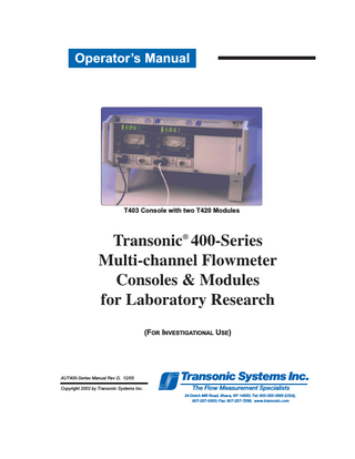
Operator’s Manual
T403 Console with two T420 Modules
Transonic® 400-Series Multi-channel Flowmeter Consoles & Modules for Laboratory Research (FOR INVESTIGATIONAL USE)
AUT400-Series Manual Rev D, 12/05 Copyright 2002 by Transonic Systems Inc.
Transonic Systems Inc. The Flow Measurement Specialists 34 Dutch Mill Road, Ithaca, NY 14850; Tel: 800-353-3569 (USA), 607-257-5300; Fax: 607-257-7256; www.transonic.com
Table of Contents Table of Contents... i Warnings & Precautions... ii Operator’s Manual I. Multi-channel Consoles A. 400-Series Consoles... I-1 B. 400-Series Modules... I-2 C. Multi-channel Flowmeter Configurations 1. T402 - Dual Channel Combinations... I-3 2. T403 - Triple Channel Combinations... I-3 D. 400-Series Flowprobes and Flowsensors... I-4 E. Multi-channel Flowmeter: General Specifications... I-4 F. Multi-channel Flowmeter: Rear Panel Diagrams... I-5 G. Module Installation & Removal in T400-Series Console... I-6 H. Synchronization: Setting up the 400-Series Flowmeter Console... I-7
II. TS410 Tubing Module A. B. C. D.
Flow Module... II- 9 Flowsensors... II- 10 Specifications... II- 11 Directions for Use: 1. Initial Bench-top Operation... II- 16 2. Meter Options... II- 20 3. Sensor Options... II- 21 4. Use of Clamp-on Tubing Flowsensors... II- 22
III. TS420 Perivascular Module A. B. C. D.
Flow Module... III- 23 Flowprobes... III- 24 Specifications... III- 25 Directions for Use: 1. Initial Bench-top Operation... III- 30 2. Flowmeter Operation... III- 32 3. Flowprobe Operation... III- 33
IV. Guarantee, Service, Warranty... IV- 35 IV. Factory Repair... V - 36 Appendix A: Precision Flowprobe and Flowsensors for 400-Series Precision Perivascular Flowprobes... A - 2 Precision Clamp-on Tubing Flowsensors... A-11 Precision Inline Tubing Flowsensors... A-14
Appendix B: Technical Notes General TN-30 Transit-Time Ultrasound Theory of Operation... B - 1 TN-94 Frequency Response... B - 2 TN-95 Data Acquisition for 400-Series... B - 3
Perivascular Flow Measurement TN-29 Extending Probe Life ... B-4 TN-5 Bench Calibration... B - 5 TN-9 Acoustical Couplants ... B-7 TN-26 Keys to Flowprobe Accuracy ... B-8 TN-16 A-Series Flowprobe Validation... B - 10 TN-28 Cardiac Output Flowprobe Use ... B - 11 TN-23 V-Series Flowprobe Use... B - 13 TN-101 Custom Programming for Graft Materials and Other Conditions... B - 15 TN-99 Extension Cable Use: Effects in Probe Received Signal... B - 16 TN-92 Electronic Swivel Tether Use with Transonic Flowprobes for Rats... B - 18 I1009 Nanoprobe Care... B - 20
Tubing Flow Measurement TN-27 Flowsensor Tubing Acoustics... B - 21 TN-34 Syringe Calibration for Tubing Flowsensor Calibration... B - 22 TN-31 Inline Sensor Care... B - 23
Transonic Systems Inc. Tel: 800-353-3569(USA); Fax 607- 257-7256; www.transonic.com Europe: Tel: 31 43 407 7200; e-mail: info@transonic.nl; Fax: 3143 407 7201
AUT400-Series Manual, page i
Warnings & Precautions ✔
Read manual before use. Failure to follow the instructions and the Warnings and Precautions below may result in risk of fire or electric shock.
✔
Transonic Research flowmeter consoles, flowmeter modules and compatible probes are designed only for investigative use with animals and are not for use in humans. For all human applications, only use Transonic products designated by the prefix “H’ in the model or series number (i.e., HT312 (single channel medical flowmeter), HQC6MP (6 mm Handle Flowprobe), etc.)
✔
Transonic perivascular Flowprobes are designed for acute and chronic implants in animals. Excessive vessel manipulation or constrictive Flowprobe fit may cause vessel spasm or damage and thus should be avoided. Recalibration of Flowprobe is necessary if the Flowprobe is to be used at different temperature or on a liquid other than the one for which it was calibrated.
✔
Transonic inline Flowprobes are designed for laboratory use only. Factory or on-site recalibration of the Flowprobe is necessary if the Flowprobe is to be used at a different temperature or on liquids other than the ones for which it was calibrated.
✔
Transonic sterile tubing Flowsensors are designed for measuring liquid flow in tubing and should not be applied to blood vessels or other internal ducts. They should be used only on tubings and for liquids for which they were calibrated. Sterile tubing Flowsensors are not designed to measure liquid flow in metal or hard plastic pipes or to measure non-liquid (gaseous) fluid flow. Transonic sterile tubing Flowsensors should not be immersed in liquids for extended periods of time. Factory or on-site recalibration of a Flowsensor is necessary if the Flowsensor is to be used on a different tubing, liquid or temperature other than for which it was calibrated.
✔
Safe and effective use of the Transonic flowmeter depends on correct application technique, adequate precaution and readiness for emergencies. Prevent vapors from entering the meter.
✔
The flowmeter is fragile. It must be transported and stored at temperatures between -40ºC - 70ºC. Rated altitude: 2000 meters.
✔
SAFE ELECTRICAL USE • Use only with grounded power receptacle to reduce risk of shock. • Position instrument so that rear panel switch and plug are accessible for quick disconnect. • Do not turn on console unless modules are installed and panel covers are in place for empty module slots. • Install only Transonic modules in the 400-Series Consoles. • Do not remove or replace modules with power turned on. • All repair on console or modules must be performed by qualified electrical technicians authorized by Transonic Systems, Inc. • Keep flammable liquids and vapors away from meter. They may cause a fire in the meter. WARNING
DEFINITION
Attention, consult accompanying documents CE Conformity Mark
0086
ii
TRANSONIC NOTATION The specific directions in this manual and in the package inserts included with each Flowsensor must be observed. Periodic testing of Flowsensors must be performed to assure the validity of flow measurements. This flowmeter conforms to 73/23 EEC. Transonic Systems is an ISO9001/EN46001-certified facility.
Dangerous voltage
The flowmeter may not be modified or serviced except by qualified Transonic repair persons.
Not category AP equipment
Danger: Explosion risk if used with flammable anesthetics.
Equipotentiality
This ground pin is connected to the metal cabinet of the monitor. It provides the User with a signal ground reference point.
AUT400-Series Manual
Section I. 400-Series Multi-channel Flowmeters T402 Consoles T403 Consoles Transonic Systems’ 400-Series Multi-channel Flowmeter Consoles and Flowmeter Modules: Introduced in 2001, this new generation of animal research volume flow measurement devices, senses liquid volume flow: 1) in vessels with perivascular Flowprobes or 2) in tubing with inline and sterile tubing Flowsensors. The modular 400-Series allows researchers to configure multiplechannel flowmeters with mix and match capabilities to fit individual application requirements. The 400-Series utilizes gold standard transit-time ultrasound technology T402 Console with two installed modules which is largely independent of vessel diameter, flow velocity profile, turbulence and hematocrit. Additional acoustical velocity phase signals are available for experimental ultrasound dilution measurements; applications include density measurement and cardiac output.
A. 400-Series Flowmeter Consoles Multi-Channel Console: 2 channel (T402) and 3 channel (T403) cases with card guides for flowmeter modules include proprietary backplane with power supply and terminal block analog outputs for signal data collection. Consoles are line powered with convenient carrying handles and tiltable front feet.
Transonic Systems Inc. Tel: 800-353-3569(USA); Fax 607- 257-7256; www.transonic.com Europe: Tel: 31 43 407 7200; e-mail: info@transonic.nl; Fax: 3143 407 7201
AUT400-Series Manual, page 1
I-B. 400-Series Multi-channel Flowmeters B. 400-Series Electronic FlowMeter Modules Tubing (TS410) and Perivascular (TS420) Flowmeter Modules are compatible with 400-series consoles.
1. TS410 Transit-Time Tubing Flowmeter Module The TS410 plug-in module operates inline and sterile tubing Flowsensors for volume flow measurement in tubing circuits, flow chambers and isolated organ apparati. The module automatically identifies the size and scale of the attached Flowsensor connected to it. Front panel button switches navigate two modes of operation: • Measurement & Status Mode: LCD text displays Flowsensor information and status while the digital display reports average volume flow. • Program Mode allows the user to select preconfigured calibration options, change the gain to recalibrate the Flowsensor onsite, and set TS410 Module parameters and alarms. Acoustical velocity phase signals are also available for ultrasound dilution measurements.
2. TS420 Transit Time Perivascular Flowmeter Module The TS420 plug-in module operates perivascular Flowprobes for instantaneous volume flow measurement in arteries, veins and ducts. The module automatically identifies the size, scale and calibration of the Flowprobe connected to it. A digital display, analog meter, and analog signal outputs present flow readings (pulsatile and average), test/error messages and calibration signals. Acoustical velocity phase signals are also available for ultrasound dilution measurements. Front panel button switches engage four modes of operation: • Test Mode: analyzes the ultrasonic performance of the Flowprobe • Measure Mode: displays volume flow •
TS420 Module
Zero & Scale Modes: calibrates external data recording devices
AUT400-Series Manual. page 2
I-C. 400-Series: Configurations cont. C. Multi-channel Flowmeter Configurations ------------------- Flowmeter consoles and modules may be mixed and matched to meet individual application requirements. Components are sold individually or in preconfigured combinations.
Flowmeter Consoles T402 Dual Channel Console with power supply T403 Triple Channel Console with power supply
Flowmeter Modules TS410 Tubing Flowmeter Module (T-suffix below) TS420 Perivascular Flowmeter Module (P-suffix below)
T402 - Dual Channel Combinations ---------------------- T402-PP: Dual Channel Flowmeter Console with two TS420 Perivascular Modules T402-PT: Dual Channel Flowmeter Console with one TS420 Perivascular Module & one TS410 Tubing Module T402-TT: Dual Channel Flowmeter Console with two TS410 Tubing Modules
T402-PB: Dual Channel Flowmeter Console with one TS420 Perivascular Module & one blank slot for further expansion T402-TB: Dual Channel Flowmeter Console with one TS410 Tubing Module & one blank slot for further expansion
T403 - Triple Channel Combinations ------------------- T403-PPP: Triple Channel Flowmeter Console with three TS420 Perivascular Modules T403-PPT: Triple Channel Flowmeter Console with two TS420 Perivascular Modules & one TS410 Tubing Module T403-PTT: Triple Channel Flowmeter Console with one TS420 Perivascular Module & two TS410 Tubing Modules T403-TTT: Triple Channel Flowmeter Console with three TS410 Tubing Modules T403-PPB: Triple Channel Flowmeter Console with two TS420 Perivascular Modules & one blank slot for future expansion
T403-PTB: Triple Channel Flowmeter Console with one TS420 Perivascular Module & one TS410 Tubing Module & one blank slot for future expansion T403-TTB: Triple Channel Flowmeter Console with two TS410 Tubing Modules & one blank slot for future expansion T403-PBB: Triple Channel Flowmeter Console with one TS420 Perivascular Module & two blank slots for future expansion T403-TBB: Triple Channel Flowmeter Console with one TS410 Tubing Module & two blank slots for future expansion
Transonic Systems Inc. Tel: 800-353-3569(USA); Fax 607- 257-7256; www.transonic.com Europe: Tel: 31 43 407 7200; e-mail: info@transonic.nl; Fax: 3143 407 7201
AUT400-Series Manual, page 3
I-D. 400-Series Flowprobes & Flowsensors D. 400-Series Flowprobes and Flowsensors Transonic Flowprobes and Flowsensors connect to flowmeter modules by the probe’s flexible cable or extension cable. Two or four ultrasonic transducers within the probe housing alternately transmit and receive a minimum level of ultrasound through a rectangular sensing window and sense volume flow of all liquid passing through the window, irrespective of where the flow occurs within the window. Transonic transit-time Flowprobes are known for low and stable zero flow offset and high resolution. Transonic Flowprobes can measure flow in aqueous, non-aerated fluids and do not require particulate content or ionization of the monitored liquid. See the Appendix for Flowprobe/Flowsensor specifications for each module.
Transit Time Ultrasound Theory of Operation Perivascular
Tubing
Cable
Sensor Body Transducer
Probe Body
Cable Cable
Transducer
Tubing
Vessel Reflector
Reflector
Transducers
How It Works! TRANSIT TIME ULTRASOUND TECHNOLOGY The transducer (a piezoelectric crystal) within the Flowprobe emits sound rays to form an ultrasound beam. As the beam traverses a vessel, each ray undergoes a phase shift in transit time proportional to the average velocity of the liquid times the path length over which this velocity is encountered. With wide-beam ultrasonic illumination the receiving transducer sums (integrates) these velocity - chord products over the vessel's full width and yields volume flow.
AUT400-Series Manual, page 4
I-E. 400-Series Console Specifications E. Multi-channel Flowmeter Specifications GENERAL FEATURES WEIGHT/ SIZE
T402 Dual Channel Console 5.21”high x 9.25” wide x 12” deep, 5.8 lbs. T403 Triple Channel Console T403 Console without Modules 5.21” high x 13.46” wide x 12” deep, 7.6 lbs
BENCH-TOP MODEL
Consoles have side panel handles and tiltable front feet for easy viewing
MODULE COMPATIBILITY Accepts 400-Series Flowmeter Modules ELECTRICAL ISOLATION
Flowmeter console is grounded. If accidentally left ungrounded, line to ground leakage current is less than 50 microamperes.
POWER
AC Input: Fuses:
POWER CORD
USA/Japan: Feller 458-H161 or equivalent Europe: Feller 199-000 or equivalent United Kingdom: Feller 209-000 or equivalent Australia: Feller 198-000 or equivalent
MODULE CAPACITY
T402 Dual Channel Console: Accepts 2 wide flowmeter modules of 20HP width or 4 narrow flowmeter modules of 10 HP width or a combination of wide and narrow modules.
MODULE CAPACITY
T403 Triple Channel Console: Accepts 3 wide flowmeter modules of 20HP width or 3 narrow flowmeter modules of 10 HP width or a combination of wide and narrow modules.
100-240 VAC; 50-60 Hz, 50 watts 0.8 Amp fast blo, mfg bussman # GMA0.8, 250 VAC
CONSOLE TO MODULE CONNECTION 96-pin DIN connector on proprietary backplane SIGNAL OUTPUT
backpanel screw terminal block to receive signal outputs from module(s) via DIN 96-pin connection with console; 12 output connections per flowmeter module, two dedicated for ground; See module specifications for signal definition and voltage rating. Use with general purpose hookup wire; stranded wire is preferred Wire: UL 1007 or equivalent; 24- 14 gauge Minimum strip length: 6 mm (.236 inches)
AUDIBLE ALARM
Beeping alarm, non-adjustable volume. Trip level, on/off setting activated through TS410 program.
Transonic Systems Inc. Tel: 800-353-3569(USA); Fax 607- 257-7256; www.transonic.com Europe: Tel: 31 43 407 7200; e-mail: info@transonic.nl; Fax: 3143 407 7201
AUT400-Series Manual, page 5
I-F. 400-Series Console Specifications cont. F. 400-Series Flowmeter Consoles Rear Panels REAR PANEL T402 FLOWMETER CONSOLE Screw Terminal Block Analog Outputs
Power On/Off Switch
Universal Power Supply
Serial Number Location
Ground
Legend
Foot
REAR PANEL T403 FLOWMETER CONSOLE Screw Terminal Block Analog Outputs
Power On/Off Switch
Universal Power Supply
Serial Number Location
Ground
Legend
Foot
AUT400-Series Manual, page 6
I-G. 400-Series Console Specifications cont. G. Synchronization: Setting Up the 400-Series Modular Flowmeter Console INTERNAL 400 MODULE SWITCH Flowmeter modules have a (labelled T400/T500) switch on the rear panel that is not accessible until the module is pulled out of the console. This switch must be set to “T400” (in the down position) before the module is inserted in the T402 or T403 console. This sets the timing of the flowmeter module to be synchronized. If the switch has been jostled or bumped out of the “T400” position during shipment , the flowmeter may exhibit considerable drift in Measure Mode and low or no signal from the Flowprobe or Flowsensor. The Synchronization Mode of 400-series modules must be selected via jumper cables on the console’s back panel terminal blocks. SELF-TRIGGERING: Connect Terminal block pin 11 to pin 12 via jumper “Synch In” to “Synch Out” on same terminal block This gives the lowest flow noise and is selected when a flowmeter module runs by itself, or multiple Flowprobes on multiple modules run simultaneously with sufficient distance (20 cm) between probes. (Flowmeter modules are shipped from the factory in self-trigger mode unless otherwise specified.)
SEQUENTIAL TRIGGERING: Interconnect the 2 or 3 flowmeter modules on the rear panel with jumpers between modules (pins 11 & 12) from “Synch In” and “Synch Out” as shown. Note: Be careful to choose the active terminal connections that correspond to the installed modules (TS410 & TS420 modules use the odd numbered terminal connector positions.) This wiring avoids the flow offsets that could result from ultrasonic cross-talk between adjacent probes.
12 ø
Slot 4
Slot 3
Synch In Sync Out GND
11 ø
ø
INACTIVE
INACTIVE
2 - Module Synchronization 12 ø
Slot 2
Slot 1
11 ø
ø
GND
ø
Slot 6
Slot 5
12 ø
12 ø
ø
INACTIVE
Sync Out
12 ø
INACTIVE
Synch In
INACTIVE
3 - Module Synchronization
Slot 4
Slot 3
Slot 2
Slot 1
11 ø
11 ø
11 ø
ø
Transonic Systems Inc. Tel: 800-353-3569(USA); Fax 607- 257-7256; www.transonic.com Europe: Tel: 31 43 407 7200; e-mail: info@transonic.nl; Fax: 3143 407 7201
AUT400-Series Manual, page 7
Blank page
AUT400-Series Manual, page 8
Section II. TS410 Tubing Flow Module
TS410 Module
A. TS410 Tubing Flowmeter Module _______________________________________ The TS410 plug-in module operates inline and sterile tubing Flowsensors for volume flow measurement in tubing circuits, flow chambers and isolated organ apparati. The module automatically identifies the size and scale of the Flowsensor connected to it.
Transonic Systems Inc. Tel: 800-353-3569(USA); Fax 607- 257-7256; www.transonic.com Europe: Tel: 31 43 407 7200; e-mail: info@transonic.nl; Fax: 3143 407 7201
AUT400-Series Manual, page 9
II-B. TS410 Tubing Module: Flowsensors PXL-Series Clamp-on Tubing Flowsensors
B. TS410 Flowmeter Module Flowsensors ME-PXL Clamp-on Tubing Flowsensors
4-crystal sensors that clamp on the outside of tubing
Clamp-on TUBING SENSOR
TUBING SPECIFICATIONS TUBING ID
WALL THICKNESS
TUBING OD inches
mm mm inches mm Catalog # inches Transonic “precision” PXL1/8 - 5/32 3.1 - 4.0 ME 2PXL In sizes 2PXL - 4PXL ratio of tubing tubing must not exceed 1:5 for PVC; 3/16 - 7/32 4.7 - 5.5 3PXL Series clamp-on 1:3 for silicone 1/4 - 9/32 6.3 - 7.7 4PXL tubing Flowsensors 5/16 - 11/32 7.8 - 8.7 4.7 1/16 1.6 5PXL 3/16 apply ultrasound PXL-Series 6PXL 1/4 6.4 1/16 1.6 3/8 9.5 6.4 3/32 2.4 7/16 11.1 7PXL 1/4 energy through 9.5 1/16 1.6 1/2 12.7 8PXL 3/8 standard laboratory 9.5 3/32 2.4 9/16 14.3 9PXL 3/8 or extracorporeal tubing to monitor 12.7 1/16 1.6 5/8 15.9 10PXL 1/2 instantaneous and average volume 12.7 3/32 2.4 1/16 17.5 11PXL 1/2 12.7 1/8 3.2 3/4 19.0 12PXL 1/2 flow of blood, glycerine/water blood 15.9 1/8 3.2 7/8 22.2 14PXL 5/8 analogs, cell culture media, saline, 19.0 1/8 3.2 1 25.4 16PXL 3/4 buffer or other solutions. Only 1 25.4 1/8 3.2 1 1/4 31.8 20PXL ultrasonic contact with the liquid is required; clamp-on tubing Flowsensors maintain total physical and electrical isolation between the sensor and the liquid under study.
ME-PXN Inline Flowsensors Transonic Precision PXN-Series Inline Flowsensors splice into laboratory tubing from 0.046 to 1.0 inch internal diameter to directly measure instantaneous and average volume flow. The sensors are designed for general bench-top application (perfused isolated organ preparations, mock circulatory models, etc.) Inline Flowsensors are especially sensitive for measurements in low flow applications.
10
PXN-Series Inline Flowprobes 4-crystal flow through probes with a smooth, round flow round channel. Cat #
for tubing ID mm inches -------------------- ME1 PXN 1.2 3/64 ME2 PXN 1.8 1/16 ME3 PXN 2.4 3/32 ME4 PXN 3.2 1/8 ME5 PXN 4.8 3/16 ME6 PXN 6.4 1/4 ME10 PXN 9.5 3/8 ME13 PXN 12.7 1/2 ME16 PXN 15.9 5/8 ME19 PXN 19.1 3/4 ME25 PXN 25.4 1 --------------------
AUT400-Series Manual, page 10
II-C. TS410 Tubing Module: Specifications TS410 transit time tubing flowmeter
LED Display mean volume flow in L/min or ml/min
Signal Quality Indicator
LCD Display SET-UP/STATUS: displays set-up menu and program messages for flowmeter and sensor settings
Selectable Filters 0.1 Hz 10 Hz 40 Hz 160 Hz
Push-button Controls SENSOR STATUS: reads sensor eprom; selected fluid/temp, calibration gain. METER STATUS: LCD displays current flowmeter settings •invert flow “ON or OFF” •1/4 scale “ON or OFF” •Active Alarms “ON or OFF” ALARM MUTE •Alarm Audio “ON or OFF” PROGRAM NAVIGATION FOR SET-UP
Sensor connection or extension cable connector
BNC Flow Output Signal Zero Offset Adjustment Recessed “one press” button adjusts flowmeter to read zero when flow is stopped.
C. TS410 Tubing Module Specifications GENERAL FEATURES WEIGHT/ SIZE
5.125” high x 4” wide x 12” x 9.062” deep; 2.3 lbs. Module is 2 console slots (20HP) wide.
CONSOLE COMPATIBILITY 400-Series Flowmeter Consoles (T402 and T403) 500-Series Instrumentation Rack (TEAM21) Requires seating in 2 card guides 96-pin DIN connector to proprietary backplane Thumb-screw to lock into console on front panel AUTOMATIC FLOWMETER ADJUSTMENTS Sensor size identification and corresponding flow output ranges (See Flowsensor tables in Appendix) Volume flow calibration of applied sensor; serial number displayed of active Flowsensor SET/UP STATUS PROGRAM PARAMETERS STATUS MODE: White button labels - Status message displayed on LCD. Sensor Status: sensor type & calibration Meter Status: Active flowmeter settings & alarm status Alarm Mute: Audible alarm On/Off PROGRAM MODE: Blue button labels - - EXIT; SCROLL; SELECT. See chart (page II-19) for Program Navigation
Transonic Systems Inc. Tel: 800-353-3569(USA); Fax 607- 257-7256; www.transonic.com Europe: Tel: 31 43 407 7200; e-mail: info@transonic.nl; Fax: 3143 407 7201
AUT400-Series Manual, page 11
II-C. TS410 Module: Specifications cont. C. TS410 Tubing Module Specifications cont. ___________________________________________ SET/UP STATUS PROGRAM PARAMETERS cont. SENSOR CONTROLS Select factory preprogrammed calibration options Adjust Flowsensor gain to change calibration onsite METER CONTROLS 1/4 Flow Scale: increases flow gain by factor of 4 for low flow measurements Calibrate Scale: sets output to 0 and 1 Volt to calibrate external recording devices with scale factor flow. Invert flow: inverts polarity of analog outputs & flow display Alarms Menu: 3 level program to select, set thresholds, and activate Alarms for “Low Flow”, “High Flow” and “Received Signal” Interruption FILTER PROPERTIES
0.1, 10, 40 Hz: 2nd order Butterworth, with a third passive pole at 160 Hz 160 Hz: 3rd order Butterworth
ZERO FLOW ADJUST
momentary push button recessed to avoid inadvertent adjustment of zero flow reading
DIGITAL DISPLAY
LED: 4 Digit (14 segment); displays Volume Flow/Sensor data/Error Messages Bar Indicator Light: Displays received signal amplitude for continuous monitoring of sensor signal quality
LCD DISPLAY
One line 16-character alpha numeric LCD displays program parameters, sensor & meter status, alarm settings. Default displays sensor serial number.
FLOW OUTPUT
Front panel mounted BNC output connector & rear panel terminal block: Pulsatile/Average Volume Flow Filtering controlled by front panel selectable filters Voltage range: -5 to + 5 volts Calibration Modes (see page II-14) Output resistance: 500 Ohm Full Range for Flow: -5 to +5 V (bidirectional flows, with range of 5 x scale factor flow)
MODES OF OPERATION (See page II-14) SENSOR CONNECTOR Front panel 16-pin connector Accepts research inline and sterile tubing Flowsensors and extension cables with male ODU 16-pin connectors. AUTOMATIC DIGITAL SENSOR IDENTIFICATION & CALIBRATION TS410 circuitry reads sensor operational data (size, scale & calibration) programmed in the sensor’s EPROM.
AUT400-Series Manual, page 12
II-C. TS410 Module: Specifications cont. C. TS410 Tubing Module Specifications cont. ___________________________________________ ULTRASONIC FREQUENCY RANGE 600 KHz to 14.4 MHz Sensor size dependent – see sensor specification tables FLOWSENSOR COMPATIBILITY Accepts Transonic “Precision” Tubing Flowsensors with 16-pin ODU connectors ME-prefix: Extracorporeal Sensors for 400-Series Flowmeters. PXL-Series: Precision XL-Series Sterile Tubing Flowsensors with 4 transducers PXN-Series: Precsion XN-Series Inline Flowsensors with 4 transducers N-Series: T106/T206 2-transducer Inline Flowsensors SIGNAL OUTPUTS
8 accessible signals via 400-series Flowmeter Console’s back panel odd numbered terminal block connection: Pulsatile Volume Flow; Mean Volume Flow; Received Signal Amplitude (2); Phase (4)
SYNCHRONIZATION Module rear panel switch for selecting synchronization mode “T400” position: T400-series flowmeter consoles use this setting. “T500” position: Utilized for 500-Series backplane synchronization by TEAM21 program and backplane processor T400-Series Multi-Module synchronization via jumper cables between console’s back panel terminal block connections:” Self-triggering Mode: “SYNCH IN” to “SYNCH OUT” jumper on each module: Sequential Triggering Mode: “SYNCH IN”crossed to “SYNCH OUT” between modules. (See console directions for use for complete synchronization instructions (page I-7)
Transonic Systems Inc. Tel: 800-353-3569(USA); Fax 607- 257-7256; www.transonic.com Europe: Tel: 31 43 407 7200; e-mail: info@transonic.nl; Fax: 3143 407 7201
AUT400-Series Manual, page 13
II-C. TS410 Module: Specifications cont. C. TS410 Tubing Module Specifications cont. ______________________________________ TS410 FLOWMETER MODES OF OPERATION OUTPUTS MODE
1
2
LCD DISPLAY
LED DIGITAL DISPLAY
Mean & Pulsatile Flow3
Average flow in ml/min or L/min
Flow = Recorded Voltage x Scale Factor
with functioning sensor
STATUS
Flow Module & Sensor Identification
Bar indicator shows signal quality Flowsensor calibration parameters Meter settings
PROGRAM SENSOR
Select and change calibration gain
PROGRAM METER
1/4 flow scale Calibrate Ø Volt scale Calibrate 1 Volt scale Invert Alarm set-up LoFlow HiFlow Rec Signal
FUNCTIONAL ERROR MESSAGES
MEASURE (default)
Bidirectional flow output between -5 Volts and +5 Volts
Expands resolution of average flow display
Flow = Recorded Voltage x Scale Factor (changes scale factor x 1/4)
Ø ml/min
Ø V = Ø ml/min
Scale factor flow value
1V = Scale factor flow
Inverts value of flow display
Inverts Polarity of Voltage Signal
Default Measure Mode
1
LCD Display: module front panel LED Display: module front panel 3 Voltage Signal Ouput for Recording: 1) BNC mounted on front panel 2) Terminal Block on console rear panel 2
AUT400-Series Manual, page 14
II-C. TS410 Module: Specifications cont. C. TS410 Tubing Module Specifications cont. ______________________________________ REAR ANALOG PANEL SIGNALS Note: TS410 modules connect to terminal block outputs on the T402 & T403 rear panels for recording analog signals. TS410 modules use terminals in “ODD” number positions (T402: slots 1 and 3); (T403: slots 1, 3 and 5) 12 = SYNCH IN
Multi-flowmeter synchronization input (See Console, page I-7, for wiring instructions)
11 = SYNCH OUT
Multi-flowmeter synchronization input (See Console, page I-7, for wiring instructions)
GROUND GROUND 8 = REC AMP 1
Companion signal to 7 = REC AMP 2. Identical to REC AMP 2 for 2-transducer N-Series sensors; representing transducer pair # 1 in 4-transducer PXL & PXN-Series sensors.
7 = REC AMP 2
Ultrasound received amplitude of the two transducers of N-Series sensors, or transducer pair #2 in a 4-transducer PXL & PXN-Series sensor. 0 to 4V , 500 Ω output, 2 V = 100% signal amplitude
6 = PHASE 2 B
Same signal as 5: PHASE 2 A, but offset by + 4.5V or -4.5V. The two signals combined provide continuity and high resolution for indicator dilution signals.
5 = PHASE 2 A
Companion signal to Phase 1A: identical to Phase 1A for N-Series sensors; representing transducer pair # 2 in 4-transducer PXL & PXN-Series sensors.
4 = PHASE 1 B
Same signal as 3: PHASE 1A, but offset by + 4.5V or -4.5V. The two signals combined provide continuity and high resolution for indicator dilution signals.
3 = PHASE 1 A
A -5 to +5V (500Ω) analog output signal representative of changes in acoustic velocity of fluid between the two transducers of N-Series sensors, or transducer pair # 1 in 4-transducer PXL & PXN-Series sensors.
2 = MEAN FLOW
Average volume flow output, filtered at 0.1 Hz. -5 to + 5 V (500Ω) “Calibrate Scale Mode” (see Table, page II6) reveals the voltage-to-flow conversion factor.
1 = PULS FLOW
Pulsatile volume flow output, filtered at 10, 40, or 160 Hz per front panel setting. (160 Hz in the 0.1 Hz setting); -5 to + 5 V (500Ω) “Calibrate Scale Mode” (see Table, page II6) reveals the voltage-to-flow conversion factor.
Transonic Systems Inc. Tel: 800-353-3569(USA); Fax 607- 257-7256; www.transonic.com Europe: Tel: 31 43 407 7200; e-mail: info@transonic.nl; Fax: 3143 407 7201
AUT400-Series Manual, page 15
II-D. TS410 Module: Directions for Use 1. INITIAL BENCH-TOP OPERATION These functional tests are suggested to acquaint a new user with Transonic Systems 400-Series Flowmeters and Transonic ultrasonic Flowprobes and to check for damage incurred during shipment. If the apparatus does not function as described during this initial operation, please call Transonic Systems’ customer service or your authorized Transonic Systems provider or sales representative
a. Flowmeter Tests 1)
Verify that the console’s rear panel synchronization terminals are properly connected. (See console synchronization instructions, page I-7.)
2)
Connect console power cord to grounded power receptacle. Do not operate unless flowmeter console is electrically grounded via supplied power cable.
3)
Turn on power switch on back panel of console TS410 Tubing Flowmeter Module Digital Display will scroll TSI ¶ and display “NO.PR.” The LCD will read “TS410 Flowmeter.” Pressing menu and status buttons will change display to “No Sensor.”
4)
Connect a tubing Flowsensor to the front panel mounted self-aligning 16-pin connector. The digital display will scroll sensor size and series and signal coupling status “ No Sig.” (no signal) until liquid is present in the Flowsensor. The LCD will display sensor serial number. When liquid is present in the Flowsensor, the digital display will report average volume flow in milliliters/minute or liters/minute. Acoustic signal quality is displayed by the number of illuminated bars on the digital display and can be continuously monitored for the presence of air, or change in Flowsensor performance.
SIGNAL QUALITY INDICATORS Signal Strength Signal Quality Bar-display “REC AMP” Voltage rear panel
16
over 80%
Good
5 bars lit
60% to 80% 30% to 60% 20% to 30% 10% to 20% under 10%
Good Good Low Low No Signal
4 bars lit 3 bars lit 2 bars lit 1 bars lit no bar lit
over 0.8 V (proportional reading) under 0.1V
AUT400-Series Manual, page 16
II-D. TS410 Module: Directions for Use cont. 1. INITIAL BENCH-TOP OPERATION cont. a. Flowmeter Tests cont. 5) Check Flowmeter’s Operational Modes The TS410 Tubing flowmeter has 3 modes of operation: MEASURE, STATUS, and PROGRAM (see page II-14) MEASURE MODE ___________________________________________________________ Install a tubing sensor in a flow loop filled with liquid. Allow a sterile tubing Flowsensor to equilibrate on the tubing about 5 minutes before taking a reading. If the sensor is properly coupled, you will observe a volume flow measurement reading on the digital display and illuminated bars indicating adequate ultrasound signal transmission. With flow stopped, the flow reading will be 0 (zero) or close to 0. This is the zero offset of the sensor. The zero offset should be low, stable under stable conditions, and not exceed the value indicated on the sensor certificate of calibration. The zero offset is affected by the fluid type, fluid temperature and tubing type (if using a sterile tubing Flowsensor). Flowsensors are calibrated specifically for these parameters. A high zero offset may indicate that the sensor is being used with fluid or tubing other than that which it was calibrated for, or may indicate a change in sensor performance. After equilibration of the sensor, you may adjust the flowmeter to read zero with flow stopped by depressing the recessed “Zero Adjust.”button on the front of the module with a pointed instrument. The digital display will flash “Zero Adj.” for approximately 10 seconds while the adjustment to the circuitry is being made and the ADJ will be illuminated on the module panel indicating that the zero has been adjusted. Note: Once the zero has been adjusted, the sensor cannot be adjusted again until the sensor has been disconnected. Pressing the button a second time will not change the offset setting.
Establish flow in the tubing circuit. The digital display will now report average volume flow in milliliters/minute or liters/minute. If the sensor has been postitioned on the tube with the arrow in the direction of the flow, the reading will be positive. A negative flow value can be corrected by changing the direction of the Flowsensor or by using the “Invert” function in the flow module program (see Program Mode section). Transonic Flowsensors measure bidirectional flow and will indicate both positive and negative flow.
Transonic Systems Inc. Tel: 800-353-3569(USA); Fax 607- 257-7256; www.transonic.com Europe: Tel: 31 43 407 7200; e-mail: info@transonic.nl; Fax: 3143 407 7201
AUT400-Series Manual, page 17