Instruction and Service Manual
24 Pages
Preview
Page 1
GB
Instruction & Service Manual
ELECTRIC TOURNIQUET 4500 ELC For I.V. Regional Anesthesia (Bier’s Block)
G1011 - Issue: 21 / 03.07
VBM Medizintechnik GmbH Einsteinstr. 1 DE-72172 Sulz a. N. Germany Phone: +49 (0) 7454 / 95 96-10 Fax: +49 (0) 7454 / 95 96-33 e-mail: info@vbm-medical.de
Index Instruction Manual
Page
1
General Information
1
2
Device Delivery
1
3
Assembly and Preparations for Use: Assembly of mobile stand with basket
2
Assembly of universal clamp and protection cover
3
Mains Connection
3
4
Technical Data
4
5
Operating Instructions
4
Tourniquet Cuffs 6
Operating Instructions
5, 6
Tourniquet Device 7
Safety Instructions
7
8
Operating Instructions Digital Timer
8
9
Cleaning Instructions
8
Service Manual
Page
1
Device Check
9
2
Trouble Shooting
10
3
Replacement of Parts
11, 12
4
Spare Parts List
13, 14
5
Pneumatic Diagrams
15 - 17
6
Circuit Diagrams
18 - 20
1 General Information
2 Device Delivery
Intended Use The Tourniquet 4500 ELC is an electric unit for use with double cuffs for Intravenous Regional Anesthesia (IVRA).
Device Delivery complete with: hand inflation bulb for manual use protection cover power cable 4 m long connecting tube for Tourniquet Cuff alarm system (microprocessor controlled Tourniquet system with audible and visual alarm in case of leakage)
Instruction Manual Before use, review this manual with safety instructions carefully. This device may only be used by trained medical personnel.
Availability:
REF 19-11-500 ELC Tourniquet with stainless steel hook and protection cover
Medical Device Directive This Tourniquet Device complies with the requirements of the European Directive 93/42/EWG for medical devices.
REF 19-12-500 ELC Tourniquet as table unit, without protection cover EC-certificate The device is certified by the TÜV Product Service GmbH for quality system. For further information contact VBM or visit our website: http:www.vbm-medical.de Download QM-Certificates EC-Certificate Device Class IIa
REF 19-13-500 ELC Tourniquet with universal clamp and protection cover
REF 19-15-500 ELC Tourniquet on mobile stand with basket and protection cover
Note Technical modifications reserved! Within the EU waste management has to be carried out according to regulation 2002/96 EG (WEEE-Regulation) In case of interference with other devices, proceed as follows: 1. Increase the distance between both devices. 2. Contact the manufacturers of the devices. Each Tourniquet device is checked for electrical safety according to IEC 601-1 (DIN EN 60 601-1). We confirm to keep within the limits of device class I, BF-type: Protective Earth Resistance < 0.1 Ohm Earth Leakage Current N.C. < 0.5 mA Enclosure Leakage Current N.C. < 0.1 mA Patient Leakage Current N.C. < 0.1 mA Repairs, which are not described in this Service Manual, have to be effected by VBM. To check the display accuracy of the calibrated gauges, VBM offers a test gauge REF 20-18-666.
REF 19-22-500 ELC Table unit on mobile stand with basket, without protection cover
Tourniquet Cuffs and further accessories are not included in the device delivery and have to be ordered separately. Detailed product information is available at VBM.
-1-
3 Assembly and Preparation for Use5-500 Assembly of mobile stand with basket REF 19-15-500 ELC
Assembly of mobile stand with basket for table unit REF 19-22-500 ELC
Insert the metal disc (6) into the base (1). Attach the aluminium legs with lock-type rollers (2) to the base (1). Attach the aluminium legs with ordinary rollers (3) to the base (1). Fasten the aluminium legs with five hexagon socket screws M8x40 (4) and five lock washers (5) using the hexagon socket wrench (7). Insert the correct side of the support rod (8) (with groove) (12) into the base (1). Attention: The cone (15) of the metal disc has to click into the groove (14) of the support rod. Fasten the hexagon socket screw M8x22 (9) with the lock washer (10) to the base (1) using the hexagon socket wrench (11).
For assembly of mobile stand see „Assembly of mobile stand with basket REF 19-15-500 ELC“ Fix the square rail by means of the two hexagon socket screws to the support rod (see a) Screw the fixation plate with hexagon socket screw M6x10 to the support rod (see b)
b
a
Screw the fixation plate with the 3 hexagon socket screws M6x10 to the lower device housing (see c).
c
Attach the basket to the square rail (see e) with the steel hook (see d)
Attach the fixation plate with basket with both hexagon socket screws M6x10 to the upper device housing.
d e
Place the Tourniquet device with the fixation plate and basket onto the support rod. Insert the attached hexagon socket screw M8x25 with the washer through the fixation plate into the support rod. Fasten the screw using the hexagon socket wrench. -2-
3 Assembly and Preparation for Use Assembly of the universal clamp (REF 19-13-500 ELC)
Mains Connection Check that the mains switch on the front panel of the device is switched off (switch position “0”).
Screw the universal clamp with the enclosed hexagon socket screws M6x25 either vertically or horizontally to the upper housing of the device. The Tourniquet device can then be fixed to the rail of the operating table or drip stand.
Plug the attached power cable into the back of the device and then plug the other end of the cable into the mains socket. Always use a shockproof mains socket. If local safety regulations require, connect the device to a potential equalisation line or an earth connection (see the Potential Equalisation Terminal on the back panel of the device).
Disassembly and assembly of the protection cover Detach the cover in the following manner: The cover is placed on the device top Pull out both shafts with flat nose pliers outside from the bearing bushes
Assemble the protection cover as follows: Place the protection cover on the device top. Make sure that the coil tubing is positioned through the gap of the protection cover Push both fixation shafts as far as possible into the fixation holes by using a drift punch
-3-
4 Technical Data
5 Tourniquet Cuffs
Weight (table unit)
7.62 kg
Dimensions Height Width Depth
150 mm 320 mm 300 mm
Mains voltage (optional)
230 V AC (100 / 110 V AC)
Mains frequency
50 – 60 Hz
Power consumption
100 VA
Fuses
2 x 2 A (T)
Protection class (IEC 601-1)
I, type BF
Operating pressure
2 bar
Regulation range
0 – 600 mmHg
Regulation accuracy
2 – 3 mmHg
Adjusted pressure limit
600 mmHg
Display accuracy of the gauge
± 10 mmHg
VBM offers the following Double Cuffs for the Tourniquet Device 4500 ELC :
Fabric Cuffs With fabric cover, silicone bladder and plastic splint (REF 20-50-xxx) Silicone Cuffs with velcro cover, silicone bladder, silicone splint (REF 20-60-xxx) with silicone bladder, silicone splint and strap with buckle (double REF 20-90-xxx) VBM Double Cuffs are colour coded blue (proximal chamber) and red (distal chamber).
Attachment and Securing of the cuff
See instructions for use included with each VBM Tourniquet Cuff.
Warning Time Alarm
Audible alarm when time reaches zero (countdown function)
Pressure Alarm
audible and visual alarm indicates leakage in the Tourniquet system
Noise level
< 70 dB (A)
Connection Tourniquet System
blue / red coil tubing with female positive locking connector
Choose the adequate cuff pressure depending on cuff size and systolic blood pressure of the patient to guarantee a safe bloodless field and to avoid harm to the patient. Cuff must not be inflated for more than two hours!
Environmental conditions: Transport/Storage
-10 ... +60°C
Operation
+10 ... +40°C 30 ... 95% atmospheric humidity without condensation
-4-
6 Operating Device
Instructions
Tourniquet
After securing the Double Cuff, the Tourniquet device has to be operated as follows: 1. Set the precision clockwise to zero.
pressure
regulator
Alarm System The microprocessor controlled alarm system which is indicated by a red flash light and an audible warning signal will be activated in the following cases:
anti-
In case of leakage inside the Tourniquet system, which means a pressure decrease of 15 mmHg compared with the nominal value
2. Switch on the device (position “I”). The power control lamp of the mains switch illuminates green and the red alarm light will illuminate for a few seconds. During this time the device cannot be operated.
If an alarm is activated, check the actual cuff pressure on the gauge. If a pressure decrease is displayed, please operate according to the safety instructions.
3. Connect the double cuff with the positive locking connectors of the device (pay attention to the colour code).
The alarm signal (red flashing light and audible warning signal) can be switched off temporarily by pressing the alarm button.
4. Turn the switch valve to “Proximal”. 5. Inflate the blue proximal chamber first. The actual cuff pressure is displayed constantly on the gauge of the device.
Manual Use (Safety System)
6. The proximal cuff pressure can be regulated via the pressure regulator at any time.
The Tourniquet device can also be operated in the manual mode with the hand inflation bulb. This offers two advantages:
7. After injection of the local anesthetic the distal chamber has to be inflated by turning the switch valve from “Proximal” to “Distal”. The distal chamber will now automatically be inflated to the same pressure as the proximal chamber. Both gauges will then indicate the same cuff pressure. The distal cuff pressure can be regulated with the pressure regulator at any time.
It is possible to disconnect the Tourniquet device from the mains supply in order to transport the patient with the Tourniquet in situ. In case of a power failure the operation can be continued safely.
8. The proximal chamber can now be deflated via the flush button on the right side.
In case of power failure or disconnection from the mains supply the Tourniquet device automatically changes into the manual mode. The device is still operational. This means:
9. After the operation the cuff has to be deflated slowly by turning the pressure regulator anticlockwise to zero.
1. The set cuff pressure remains constant in the Tourniquet system. 2. Further inflating of the cuff has to be done via the hand inflation bulb. 3. The cuff can be deflated by pressing the red (distal) or blue (proximal) flush button.
-5-
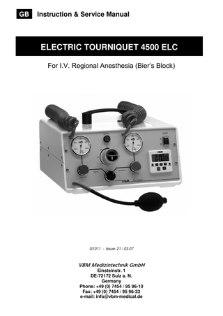
6 Operating Instructions Tourniquet Device c) Alarm button
a) Color Coded Coil Tubing (red and blue) with positive locking connectors; built into the device, therefore absolutely leak proof
audible and visual alarm will be activated in case of leakage in the Tourniquet system
b) Analogue Gauge pressure range from 0 to 600 mmHg, always displays the actual cuff pressure
a
d) Mains Switch Compressed Air / Manual Mode
c
d b
g
e h
e) Flush Button (red and blue) Pushing deflates the cuff immediately, releasing inflates the cuff back to the set pressure; excellent to check for bleedings and also for releasing anesthetic gradually after I.V. Regional Anesthesia
i
f
f) Switch valve Allows quick and exact switching from the proximal to the distal cuff
g) Digital Timer Countdown timer with alarm
h) Precision Pressure Regulator precise pressure regulation; automatic pressure compensation; safety knob prevents accidental movement; pressure range from 0 to 600 mmHg
-6-
i) Manual Safety System with Hand Inflation Bulb changes automatically into manual mode in case of power failure
7 Safety Instructions Operating Always check that the pressure regulators are set to zero before switching on the device. Never occlude the tubings between device and cuff. Make sure that the cuff inflates properly by manual palpation. Check the cuff pressure continuously during the operation. The gauge of the device always displays the exact cuff pressure. Any pressure decrease is indicated on the gauge and activates the alarm.
Mains Connection Connect the Tourniquet device only to a grounded AC mains supply that complies with IEC requirements. Always use a three-pole cable. Connect the device to a power supply that corresponds to the input requirements indicated on the ratings plate on the back panel of the device.
Warning Do not use the Tourniquet in explosion hazarded areas, which can be caused by flammable anaesthetics and disinfectants.
If the alarm is activated, operate as follows: Switch off the alarm signal by pressing the alarm button. Check the pressure constancy on the gauge. Inspect the cuff, the tubes and connections for damage. Check for firm connections. If the alarm system is activated again the device has to be inspected as described in "Service“
Splashing Water Protect the Tourniquet device from splashing water. The power socket on the back of the device has to be kept dry. Do not use the device if any liquid has entered it.
Attention Make sure to select the correct cuff size. VBM offers a complete range of Tourniquet Cuffs. Ensure that there is compatibility between the fittings, when using cuffs of other manufacturers. Also ensure that damaged cuffs and connectors are no longer used. Make sure that the red chamber of the VBM Double Cuff is put on distally.
Manual Use The manual mode and pressure regulator are independent from each other. If the device is connected to the power supply and switched on, the cuff will inflate to the setting of the pressure regulator regardless from the pressure adjusted via the hand inflation bulb. Therefore it is very important to check the position of the pressure regulator. Consider that in the manual mode possible leaks will not be compensated automatically. The alarm is also switched off. Therefore the device should normally be used with power supply. The manual safety system is only an additional option in case of power failure.
Before Use Check the functionality and air tightness of the Tourniquet system before each use. Put the cuff around a bottle and inflate to the maximum pressure of 600 mmHg. Switch off the device with the mains switch and check the pressure constancy of the Tourniquet system on the gauge. The pressure on the gauge should not decrease more than 30 mmHg within 5 minutes. In case of pressure decrease of more then 30 mmHg, check the device according to page 9.
-7-
8 Operating Instructions Digital Timer
9 Cleaning Instructions Tourniquet Device
2 1
Switch off the device (position “0”) and disconnect the power cable, before cleaning the device!
3
Cleaning Wipe the device with a soft and damp cloth. 10
4
Disinfection Wipe the device with a cloth that has been dampened with commercially available disinfectants in low concentration. Never immerse the Tourniquet unit in liquids!
9
5 6
7
8
Sterilisation Do not sterilise the Tourniquet unit!
The Digital Timer (count-up and countdown) is operated as follows: Functions of Keyboard: 1 displays time in hours 2 displays time in minutes 3 displays time in seconds 4 Clock button 5 Hour button 6 Start/Stop button 7 Minute button 8 Reset button 9 Second button 10 Timer button
Tourniquet Cuffs Cleaning, Disinfection, Sterilisation See instructions for use included with each VBM Tourniquet Cuff.
Setting the Clock: Push the Clock button for approximately 3 sec. until the digits flash in the display Push HR button to advance to correct hour; continue also with MIN and SEC button; keep the button pushed to speed up the setting Push clock button to start clock Push Start/Stop button for 3 seconds to change between AM and PM Setting Timer for Countdown: Push Timer button; Push Reset button to clear the display Push HR, MIN and SEC buttons to display the desired time in hours, minutes or seconds; Push Reset button once to correct and for new time setting Push Start/stop button to start countdown Push Start/Stop button once to interrupt countdown, then Start/Stop button once to continue the countdown. When the countdown reaches zero, an alarm will be activated (duration 1 minute); at this moment the timer will automatically count up in seconds to show the time elapsed since the alarm has been activated. The alarm and count-up can be stopped by pushing the Start/Stop button Setting Timer for Count-up: Push Timer button; Push Reset button to clear the display With timer cleared to 0:0000, Push Start/Stop button; Timer will begin counting up in seconds To stop the count-up, Push Start/Stop button once To continue the count-up, Push Start/ Stop button once more
-8-
1
Device Check Repairs
Function and Leakage check
Repairs which are not described in this Service Manual may only be carried out by VBM or the authorised VBM service. Otherwise VBM cannot be held responsible for safety, reliability and performance of the device.
c
e
b
VBM does not accept any warranty claims if the user or an unauthorised service agency has attempted to effect repairs which are not described in this Service Manual.
f
To ease repair of the device return it together with a detailed description of the defect.
h d a
As a protective measure for the safety of VBM staff return the device or cuffs completely cleaned and disinfected (see “Cleaning, Disinfection and Sterilisation”). The VBM Service is entitled to refuse the repair of contaminated items for safety reasons.
g
1. Connect the device to the mains supply. 2. Set the switch valve (a) to distal (red Coil Extension Tube). 3. Switch on the device (mains switch position “I”).The power control lamp of the mains switch illuminates green (b). The red alarm light (c) will illuminate for a few seconds. 4. Now it must be possible to adjust any desired pressure value with the pressure regulator (d) with an accuracy of 2-3 mmHg. Any pressure value has to be displayed (e). 5. Set the pressure to 600 mmHg. 6. Press the red deflate button shortly (f). The pressure drops to 0 mmHg and has to go back to the preset 600 mmHg (e). 7. Set the pressure to 0 mmHg and switch off the device. 8. Inflate to 600 mmHg with the hand inflation bulb (g) 9. Set the timer (h) to 5 min. countdown. The pressure decrease on the gauge should not exceed 30 mmHg within 5 min. In case of a pressure decrease of more than 30 mmHg follow the indications on page 10 (Leakage in Tourniquet system). 10. Turn the switch valve (a) to proximal (blue Coil Extension Tube) and repeat steps 3-9 to check the proximal side. 11. To check the display accuracy of the calibrated gauges, VBM offers a test gauge REF. 20-18-666.
-9-
2 Trouble Shooting Failure/Defect
Cause/Removal
Mains Switch The power control lamp of the mains switch does not illuminate green when in position “I“
No mains supply. Connect the device to the mains supply. Fuses on the rear panel are defective. Check the fuses and replace them if necessary (page 12).
Manometer Pointer does not move
Compressed air is missing. See mains switch. Pointer is jammed or loose. Replace the gauge (page 11). Fuses of the power board are defective. Check the fuses and replace them if necessary (page 12).
Position of pointer is not exactly on zero (tolerance 10 mmHg).
Gauge is defect. Replace the gauge (page 11).
Glass of the gauge is damaged
Replace the glass of the gauge (page 11).
Deflate Button Deflation with the blue or red button is not possible.
Deflate valve is jammed or defect. Replace the complete valve (page 12).
Digital Timer Display is too weak or not readable.
Battery is empty. Replace battery (page 12).
Alarm Leakage in the system (device with cuff).
Connectors are connected incorrectly. Press the alarm button and reconnect the connectors. Cuff is damaged. Check the device without the cuff (page 9 “Leakage check”). Replace the cuff if necessary. See “Leakage inside the device”.
Leakage inside the device
Valves (Deflate-, One-way-, 3/2-way-valve) are not air-tight. Repair by VBM is necessary
- 10 -
3 Replacement of Parts Opening the case
a
a b b
5. For table units (REF 19-12-500 ELC / 19-22-500 ELC) first the two plastic caps on the handle (a) have to be removed. 5.1 Unscrew the two hexagon screws M8x35 (b) and remove the handle. 1.
b
Attention: Pull off the mains plug before opening the case!
a
2.
Devices on mobile stand REF. 19-15-500 ELC have to be removed from the mobile stand. Therefore unscrew the hexagon socket head cap screw M8x25 (a). 2.1 Remove the basket by unscrewing the two counter bolts M5x12 (b).
6. Unscrew the six screws on the right side (a) and the six screws on the left side of the Tourniquet case. 6.1 Finally unscrew the screw M4x10 (b) on the upper part of the case. 3.
7. Pull the upper part of the case towards the top and the lower part of the case towards the bottom.
Remove the protection cover as follows: The protection cover is fitted on the case upper part. Pull out both metal shafts with flat pliers (located in the back of the device).
Replacement of the manometer
a
4. Table units on mobile stand REF. 19-22-500 ELC have to be removed from the fixation plate. Unscrew the three hexagon screws.
1. Pull off the mains plug. 2. Open the case (described above). 3. Cut the tube at the gauge. 4. Loose the nut (WAF 11) at the gauge holder (a). Remove the gauge through the front panel. Loose the metal ring anticlockwise to replace the glass of the gauge. - 11 -
3 Replacement of Parts Replace Digital Timer
Replace mains fuse
b
a
a 1. Pull off the mains plug. 2. Push up the shackle at the power socket on the rear panel with a screw driver (a). 3. Fuse socket is now loose and can be removed. 4. Replace both fuses (2 A(T) 20 x 5 mm).
1. Pull off the mains plug. 2. Open the case (page 11). 3. Disconnect the electrical connection (a).
Replace power board fuse set
4. Unscrew the four screws (b) and remove the complete Timer. Replace Battery
a a
LED
1. Pull off the mains plug. 2. Open the case (page 11). 3. Push down the fuse sockets (a) with a screw driver and loosen them by turning 60 degrees anticlockwise. 4. Remove the fuses (200 mA(T) 20 x 5 mm) and replace them.
1. Open the battery compartment on the back side of the device with a screw driver (a). 2. Remove the old battery with a screw driver and put in a new battery (pay attention to the polarity).
Replace Deflate Valve
a
1. Pull off the mains plug. 2. Open the case (page 11). 3. Cut the tubes at the deflate valve. 4. Push up the shackle with a screw driver (a).
- 12 -
4 Spare Parts List
Manometer 600 mmHg, complete with nut and glass REF 20-50-510
Manometer 300 mmHg, complete with nut and glass REF 20-50-505
Glass with 50 mm , suitable for manometer 600 mmHg and 300 mmHg REF 03-44-902
Protection cap for mains switch REF 20-15-776
Digital Stop Watch, white, for external compartment, complete with battery REF. 15-50-900
Digital Stop Watch, white, complete with battery REF 10-50-900
Spare Battery for digital stop watch, white, for external battery compartment, size AA / Mignon, U=1.5V REF. 15-50-999
Spare Battery for digital stop watch, white, size AAA / Micro, 10.5x44.5, 1.5V REF 10-50-999
3/2-way Solenoid Valve 230 V AC REF 20-50-335 3/2-way Solenoid Valve 100/110 V AC REF. 20-50-336
Mains switch without protection cap 50/60 Hz 230 V AC REF 20-15-775 50/60 Hz 100-110 V AC REF. 20-15-775/110
One-way-valve REF 20-50-575
Spring, 75 mm long, kink-protection for inflation bulb REF 20-10-336
Hand Inflation Bulb with tube and spring REF 20-10-333
Spring, 40 mm long, kink-protection for coil tube REF 20-10-449 Fuse 2 A(T) 20x5 mm REF 20-15-772
Fuse 200 mA(T) 20x5 mm REF 10-50-119-5 Washer-ring for Luer Lock Adapter, male REF SLLM40-65
Switch distal/proximal without valve REF 20-50-545
Deflate button, blue, without valve REF 20-50-540 Deflate button, red, without valve REF 20-50-530
Luer Lock Adapter, male REF CHLLM30 Positive Locking Connector, male REF SLZM30
Positive Locking Connector, selflocking, female REF SSLZF40
- 13 -
Valve for switch distal/proximal REF 20-50-570
Valve for deflate button red/blue REF 20-50-535
4 Spare Parts List
Protection Cover, suitable for – Tourniquet 2500 ELC – Tourniquet 2800 ELC – Tourniquet 2x500 ELC REF. 10-25-740
Case upper part for table unit REF. 20-16-752
Case lower part REF. 20-25-752
Metal Shaft for Protection Cover REF. 20-25-740-3
Protection Cover, suitable for – Tourniquet 4500 ELC – Tourniquet 5000 ELC – Tourniquet 5800 ELC REF. 10-25-741
Case lower part for table unit REF. 20-16-751
Coil Extension Tube, Length: 2,5 m, without connectors – colour: red REF. 20-10-442 – colour: blue REF. 20-10-444 – colour: black REF. 20-10-448
- 14 -
Case upper part REF. 20-25-751
5 Pneumatic Diagram
- 15 -
5 Pneumatic Diagram
- 16 -
5 Pneumatic Diagram
- 17 -
6 Circuit Diagram
- 18 -