WALKER FILTRATION
LASERVAC 850 Installation Operation and Maintenance Instructions
Installation Operation and Maintenance Instructions
16 Pages
Preview
Page 1
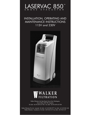
LASERVAC 850
S M O K E
™
E V A C U A T O R
INSTALLATION, OPERATING AND MAINTENANCE INSTRUCTIONS 115V and 230V
Walker Filtration Ltd, Spire Road, Glover East, Washington, Tyne & Wear, NE37 3ES England. Tel: (Intl. +44 191) 0191 417 7816 Fax: (Intl. +44 191) 0191 415 3748 Walker Filtration Pty Ltd - Australia Tel: (Intl. +61 3) 03 9439 4777 Fax: (Intl. +61 3) 03 9431 1610 Walker Filtration - Scandinavia Tel: (Intl. +45) 70 20 13 07 Fax: (Intl. +45) 70 20 11 07
GENERAL SAFETY Please ensure you read these instructions before installing or operating this equipment. Failure to do so could result in improper usage, damage to the unit and / or personal injury. Store these instructions safely.
1.
SAFETY NOTICE
LASERVAC 850 smoke evacuators are specifically designed to remove smoke plume and particulate debris. Debris is not considered to include liquid. The Liquid collection trap is provided as a cautionary measure to protect the unit from the accidental ingress of liquids.
2.
CLEANING AND DE-CONTAMINATION
Prior to any servicing or repair by Walker Filtration Ltd, ensure that the LASERVAC 850 smoke evacuator has been de-contaminated and a notice accompanies the machine to this effect. The machine should be surface cleaned with a damp cloth and disinfectant. All tubing, filters and the liquid trap must be removed and disposed of in accordance with relevant procedures prior to return to Walker Filtration or authorised distributor for servicing.
PAGE 01
SYMBOLS
•
•
On/Off Button
Service indicator warning light SERVICE
FLOW UP
Increase flow rate / speed Digital display. Speed range 0 to 9 Decrease flow rate / speed
FLOW DOWN
Primary filter service life indicator. (Gradually increases in scale).
PRIMARY FILTER LIFE
Secondary filter service life indicator. (Gradually increases in scale).
SECONDARY FILTER LIFE
CE mark, in accordance with Medical Electrical Equipment, General requirement for safety
ETL mark, in accordance with UL2601 :1994:1, Medical Equipment General Requirement For Safety.
LASERVAC 850 classified as Type B Equipment, in accordance with the Medical Electrical Equipment, General Requirement for Safety.
PAGE 02
CONTENTS 1. 1.1 1.2 1.3 1.3.1 1.3.2
GENERAL Introduction Features Standards and Approvals 230V - LASERVAC 850 115V - LASERVAC 850
2. 2.1 2.2 2.2.1 2.2.2 2.2.3 2.3 2.4 2.4.1 2.4.2 2.5 2.6
DESCRIPTION General Membrane control panel Variable speed control Filter monitoring Service Indicator Vacuum pump High efficiency filtration Primary filter Secondary bacterial filter Liquid trap Pneumatic foot switch
3. 3.1 4. 4.1 Fig. 1 Fig. 2
ACCESSORIES Starter pack ELECTRICAL SYSTEM Electrical connection 115V Electrical Drawing 230V Electrical Drawing
4.2 4.3 4.4
Electrical fuses Electrical switch Thermal cut out
5. 5.1 5.2
OPERATING SYSTEM Performance Noise levels
6. 6.1 6.2
COMMISSIONING Check procedures Initial start up
7.
SAFETY PRECAUTIONS
8. 8.1 8.2 8.3 8.4
MAINTENANCE Service Indicator warning light Routine Storage Transportation
9. 9.1
FILTER AND LIQUID TRAP REPLACEMENT Filter replacement indicator
10.
GUARANTEE
11.
PROBLEM SOLVING
12.
LASERVAC 850 SPECIFICATION 00 PAGE 03
1. GENERAL
1.1 Introduction It is now internationally recognised, that aerosols and particulate debris produced from laser or electro-surgery procedures provide a risk to safe operating practice and can contaminate the operating environment with harmful pollutants. The LASERVAC 850 provides the most effective solution to the problem of unpleasant smoke and odours created by such procedures. Walker Filtration are a world leader in the field of medical laser smoke extraction equipment and LASERVAC smoke evacuators are installed into hospitals and clinics world-wide. The LASERVAC 850 combines the proven benefits of three stage high efficiency filtration to remove aerosols, particulate matter, moisture and smoke odours. It is simple to use and is supplied with a full range of disposable filters and accessories.
1.2 Features ●
Compact and mobile design
●
Quiet in operation, <59dBA
●
High efficiency filtration, to 0.01 micron
●
Unique filter connection
●
Membrane control panel
●
Variable flow control
●
Filter life cycle monitoring
●
Service indicator
●
Integral liquid trap
●
Starter pack
●
High efficiency vacuum motor
1.3 Standards and approvals The LASERVAC 850 laser smoke evacuators are manufactured in accordance with ISO 9001 Quality Management procedures. Each LASERVAC 850 is subjected to performance testing prior to despatch and all units have been approved to relevant International standards and, carry the CE and ETL approval marks. 1.3.1 230V - LASERVAC 850 The electrical control system conforms to EN60601-1:1990, BS5724, including A13:1996. This relates to safety requirement for medical equipment and the EC Directive EMC 89/336 EEC as amended by 92/31/EEC, 93/68/EEC. All LASERVAC 850 smoke evacuators also comply with the low voltage directive 73/23/EEC. 1.3.2 115V - LASERVAC 850 The electrical control system conforms to UL2601 1st edition 1994, Medical Equipment General Requirement for Safety. It also conforms to the Canadian CAN/CSA C22.2 No. 601-1 M90.
PAGE 04 00
2. DESCRIPTION
2.1 General Designed for optimum versatility, the LASERVAC 850 has a variable flow and speed control, ensuring that it can be used in all types of laser or electro surgery, with all medical lasers. Mobile and compact, the LASERVAC 850, is self contained and portable filtration system with built in anti-static castors and handle for full manoeuvrability. The units stand vertically and have a small footprint making them ideal for any surgical setting. The LASERVAC 850 is simple to operate and utilises a soft touch display and user friendly informative control panel. The LASERVAC 850 incorporates several special features:2.2 Membrane control panel The LASERVAC 850 laser smoke evacuator incorporates a user friendly, soft touch membrane control panel. Conveniently situated, at hand level, the membrane control panel allows the operator maximum control and flexibility to suit the exact surgical procedure. The control panel features an ON/OFF button and facilitates variable speed and flow control. 2.2.1 Variable speed control At the touch of a button, the flow can be increased or decreased according to operator requirements. The flow rate is fully adjustable to maintain optimum flow rate and noise level. (See page 2) 2.2.2 Filter monitoring The membrane control panel shows clearly the operating life of the primary and secondary filter. A flashing LED, which gradually increases in scale, illustrates when a filter change is necessary. This assures optimum performance and cost effective filter replacement. (See page 2) 2.2.3 Service indicator A service indicator light provides a clear warning that the LASERVAC 850 is due for a routine annual service (See page 2). Walker Filtration offer a complete service policy. Contact the Medical Sales department, for full details. 2.3 Vacuum pump The vacuum source is a dry running, two stage “by pass” vacuum motor. This high capacity motor can run on a single phase and is available in either 230V-50Hz or 115V-60Hz electrical supply and requires no lubrication. As a protection measure the motor has a thermal cut out to prevent over heating. 2.4 High efficiency filtration All filters are safe, quick and easy to replace and no special equipment, tools or training is required. Each filter utilises high efficiency pleated media, which is housed within a surrounding casing, to ensure thorough capture of debris, particulate matter and noxious odours. The LASERVAC 850 laser smoke evacuator has a unique inter-connecting filter arrangement for complete environmental protection . All filters are disposable and can be incinerated.
PAGE 05
Primary Filter LVPF850
Secondary Filter LVSF850
2.4.1 Primary filter LVPF850 The disposable primary filter, consists of a plastic casing containing a pleated, high efficiency, filter element for removal of bulk contamination. The primary filter has an efficiency of 99.999995% at 0.01 micron, to remove debris and particulate matter created during laser surgery. The primary filter seals onto the liquid collection trap and fits directly onto the secondary filter , by a simple quarter turn knob. It is necessary to change the primary filter on a frequent basis for optimum performance. It is recommended that the primary filter is changed after two hours. The control panel has a built in service life indicator, which will flash when the primary filter is to be changed. When the primary filter is replaced the indicator will automatically re-set (see point 9). For specific information, please refer to the instruction leaflet 04 196 001 01 supplied with each new primary filter. 2.4.2 Secondary filter LVSF850 The secondary filter combines a two stage, high efficiency filter to remove viral size particles down to 0.01 micron at 99.9999995% and to adsorb obnoxious odours. The disposable filter, consists of an aluminium casing bonded to a moulded nylon end cap and contains pleated, bacterial ULPA grade and activated carbon filter media for dual purpose performance. The secondary filter is located underneath the primary filter and can be quickly released from it’s position by pressing a spring loaded clip down wards. It is necessary to change the secondary filter at least every six months. The activated carbon has a scavenging effect, which continually adsorbs odours even when the LASERVAC 850 is not in use. It is recommended that stock of the secondary filter is rotated and the “use by date” on the box is observed. (See point 9) The control panel has a built in indicator which will flash when the secondary filter should be changed. When the secondary filter is replaced the indicator will automatically reset. For specification information, please refer to the instruction leaflet 04 185 001 01 supplied with each new secondary filter. 2.5 Liquid trap LVLT850 The liquid trap is a cautionary measure to protect the LASERVAC 850 from the accidental ingress of any potential liquids. The liquid trap inserts directly into the front of the cabinet and is held in place by the primary filter. The transfer tube fits directly into the liquid trap. If the liquid approaches the MAX. level indicated on the collection trap (0.75 Ltrs/1.6 US pints) the LASERVAC 850 should be switched off at the mains immediately and the liquid collection trap replaced. In most cases, the liquid trap should be removed when it begins to show signs of discolouration. If liquids have been present, the primary filter (LVPF850) should be replaced as a matter of course. (See point 9). For specific information, please refer to the instruction leaflet 04 206 001 01, supplied with each new liquid trap.
Liquid Trap LVLT850
2.6 Pneumatic foot switch LVFS1 A pneumatic foot switch is supplied as standard. It is installed at the rear of the unit to the ‘remote connection’ socket. Once the desired flow rate has been set at the membrane control panel the LASERVAC 850 can be switched on or off as required. When the footswitch is not required it can be stored in the rear stowage compartment.
PAGE 06
3. ACCESSORIES
3.1 Starter pack Each LASERVAC 850 is supplied complete with a starter pack containing additional items required to run the unit. Each pack contains :* * * *
3 Primary Filters 1 Tube Connector 1 Funnel 1 Liquid Trap
LVPF850 LVTC2207 LVFU22 LVLT850
BOTTOM LEVEL
Tube Connector Funnel
Primary Filter
Liquid Trap
4. ELECTRICAL SYSTEM
* * * * *
Transfer Tube
1 Foot Switch 1 Mains Lead 1 Transfer tube 1 Collection wand 1 Catheter tube
LVFS1 LVML1 LVTU2215 LVWA22 LVTU0710
TOP LEVEL Foot Switch
Collection Wand
Mains Lead
Catheter Tube
4.1 Electrical connection A standard IEC 320/CEE22 mains inlet socket, with integral on / off switch is located at the rear of the machine. An ON/OFF button is also located on the membrane control panel, see point 2.2. The LASERVAC 850 is supplied complete with a safety pneumatic foot switch, which allows the smoke evacuator to be switched on or off remotely. The foot switch is connected into the “remote connection” socket, located at the rear of the machine. When not required, the foot switch can be stored in the rear stowage compartment. A 2.0 metre trailing mains lead with moulded plug is supplied, to which a suitable approved medical grade plug must be connected. An ON/OFF switch is located at the rear of the machine and is built into the IEC socket. PLEASE NOTE :Wire colour Brown Live Wire colour Blue Neutral Wire colour Yellow / Green Earth
Warning : The yellow / green earth wire must be connected.
PAGE 07
Figure 1 115V Electrical drawing CONTROL PANEL
LASERVAC 850
S M O K E
E V A C U A T O R
FILTER IND PRIM
MOTOR ASSEMBLY
SHEATH
FILTER IND SEC
MAGNETIC PROXIMITY SWITCH
I.E.C. SOCKET/SWITCH & FUSE HOLDER R.F.I HOLDER BLUE VOLTAGE SWITCH SELCT TO 115V
BROWN
TRANSFORMER
RED BLK YEL BLUE
N
BLK BLK RED ORG
L
MAINS LEAD THERMAL CUT-OUT
+-
P.C.B.
AIR SWITCH
REMOTE RED WHITE BLUE BROWN
BROWN
YELLOW/GREEN
PNUEMATIC SWITCH
BLUE PNEUMATIC FOOTBULB
Figure 2 230V Electrical drawing
CONTROL PANEL
LASERVAC 850
S M O K E
E V A C U A T O R
MOTOR ASSEMBLY FILTER IND PRIM
FILTER IND SEC
MAGNETIC PROXIMITY SWITCH
SHEATH
I.E.C. SOCKET/SWITCH & FUSE HOLDER R.F.I HOLDER BLUE VOLTAGE SWITCH SELCT TO 230V RED BLK YEL BLUE
BROWN
BLK BLK RED ORG
TRANSFORMER
R.F.I. MAINS LEAD THERMAL CUT-OUT REMOTE
-
RED WHITE BLUE BROWN
BROWN
YELLOW/GREEN
PNUEMATIC SWITCH
BLUE PNEUMATIC FOOTBULB
PAGE 08
AIR SWITCH
4. ELECTRICAL SYSTEM (Continued)
P.C.B.
4.2 Electrical fuses The Laservac 850 is protected by two anti-surge fuses, located in the IEC mains inlet at the rear of the machine. Warning - Before replacing the fuses, ensure that the LASERVAC 850 is switched off and remove the mains lead. The fuses are located in a drawer built into the mains socket. To replace, lever open the hinged facia with a small screwdriver, from the recess. This will reveal the red fuse holder drawer. Slide the drawer out with a small screw driver. This will reveal the fuses, one on the right and one on the left. Replace the old fuses, ensuring the new fuses are of the correct type and rating. See table below :Voltage
Frequency
Fuse Size
V
Hz
A
Type
230
50
5.0
5A (T) HBC - 250V
115
60
10.0
10A (T) HBC - 250V
4.3 Electrical switch The ON/OFF switch is located on the rear of the machine and is built into the IEC socket. Always switch the machine OFF when not in use and remove mains lead. The unit must always be switched off for maintenance and consumable part replacement. 4.4 Thermal cut out The LASERVAC 850 is further protected by a thermal cut out switch. If, due to any circumstance this switch trips out, it will reset itself when the machine cools down to normal operating temperature.
5. OPERATIONAL SYSTEM
Caution : If the thermal cut out operates, the machine must be disconnected from the mains power supply and allowed to cool down before being switched on again. The cooling down period will take at least 30 minutes. 5.1 Performance Under clean conditions the LASERVAC 850 will draw 850 Lm-1 (30 cfm) through a 22 mm transfer tube. When the performance level of the machine falls to an unacceptable level, the primary filter should be replaced. (Also see problem solving). For optimum performance:- ● Ensure that transfer tubes are no longer than required ● Ensure that there are no kinks in the transfer tube ● Ensure that the collection device is as close to the smoke plume source as possible
6. COMMISSIONING
5.2 Noise Levels The use of a quiet vacuum pump and acoustic cabinet provides a noise level in order of 59 dBA, measured at 1 metre. This ensures that the LASERVAC 850 can be used in close proximity to the operator and patient without any inconvenience. The Laservac 850 should be operated at the lowest acceptable speed setting to give the lowest noise level. 6.1 Check procedures The LASERVAC 850 machine has been fully tested prior to despatch, but due to possible damage in transit, the following precautions should be taken :6.1.1 Check for transport damage and shortages. Check the contents is as stated on the box label. Advise Walker Filtration, or authorised dealer, if there are any discrepancies. 00 PAGE 09
6.1.2 Check the incoming supply voltage and frequency correspond to the specifications shown on the serial plate, fixed to the reverse of the machine. 6.2 Initial Start Up CAUTION - Ensure the unit is not operated without filters installed The following procedure should be adopted :6.2.1 A 2.0 metre long mains lead is supplied in the starter pack. An IEC plug is moulded onto one end and a suitable medical grade mains plug must be connected to the other end by a competent person. Observe the label attached to the lead for wire identification. The machine must not operate without an earth connection. 6.2.2 The LASERVAC 850 should arrive assembled with a liquid trap, primary and secondary filter. (See section 2 for replacement instructions.) 6.2.3 Connect the transfer tube by pushing it firmly into the liquid trap. 6.2.4 Switch the unit on at the IEC mains socket at the rear of the unit. This will illuminate the display and the speed control will default to zero. Press the ON/OFF button, on the control panel. The adjacent LED will illuminate to indicate the unit is now on. 6.2.5 The arrow buttons above and below the numeric display panel, indicate increase and decrease of flow rate. To start the motor press the “arrow up” button. With each depression of the arrow-up button the flow rate and digital display will increase up to a maximum level of 9. To slow the motor down, press the arrow-down button below the display and, the flow will reduce in a similar manner. 6.2.6 Depressing the on-line button on the LASERVAC 850 control panel will stop the unit from running. 6.2.7 If the smoke evacuator is required to be operated remotely, the pneumatic foot switch should be connected into the rear of the unit. Once the desired flow rate has been set, the foot switch can be used to turn the unit on and off as required. When the foot switch is not required it can be stored in the rear stowage compartment.
7. SAFETY PRECAUTIONS
6.2.7 The display will remain at the speed it is set at until it is switched off at the mains switch. ENSURE THESE INSTRUCTIONS ARE FOLLOWED. 7.1 Do not use the LASERVAC 850 within the “Zone of Risk” this being an area extended from 25 cm around any part of the anaesthetic circuitry and the gas paths of any anaesthetic apparatus. Within this area, full precautions must be taken with respect to flames, hot surfaces or sparks from all causes. 7.2 Always switch the machine OFF when not in use and remove mains lead. The unit must always be switched OFF for maintenance and consumable part replacement.
PAGE 10
7.3
Always disconnect from electrical power supply after each operating session.
7.4 The primary and secondary filters contain a strong magnet. Ensure that no person fitted with a pace maker comes within one metre of the smoke evacuator or filters. 7.5 The unit is not designed to remove bulk liquid. It is designed only to catch liquids accidentally drawn into the machine. The MAX. indicator on the liquid trap should never be exceeded. 7.6 Ensure all instruction leaflets illustrating replacement details are read thoroughly and followed. 7.7 Always replace the power cord, store the foot switch and remove the transfer tube when the LASERVAC 850 is not in use. Extended cords and tubing can present a trip hazard. A stowage compartment is located at the rear of the unit. 7.8
Clean as indicated in section 8.2.
7.9 Ensure the cooling air intake vents at the rear of the unit are never blocked as this will result in the unit overheating.
8. MAINTENANCE 8.1 Service indicator warning light A maintenance indicator (see page 2) is displayed on the membrane control panel. When the indicator illuminates it reminds the operator that 12 months has elapsed and a service is now due. Walker Filtration offer a full service policy. The timer will be re-set during the service. 8.2
Routine
●
Clean machine external surfaces regularly. Clean only with a damp cloth and mild disinfectant in accordance with local procedures.
●
Replace primary filter (LVPF850)
every 1 hour, as indicated on the m e m b r a n
control panel. ●
Replace secondary filter (LVSF850)
every 6 months, as indicated on the membrane control panel.
●
Replace liquid trap (LVLT850)
see section 2.5
●
Replace tubes and connectors
as required
8.3 Storage The LASERVAC 850 is to be stored in clean and dust free environment, maximum storage temperature 35°C, minimum storage temperature 5°C, store in a vertical position. Do not stack other items on units when boxed or not boxed. 8.4 Transportation The unit must be transported in the packaging provided, the unit must be stored in the vertical position. In the event of a product return, the original packaging should be retained.
PAGE 11
9. FILTER AND LIQUID TRAP REPLACEMENT
9.1
Filter replacement indicator
The membrane control panel has a built in LED Service life Indicator for the primary and secondary filter, which increases in scale during use. The LED will flash when either the primary or secondary filter should be replaced. Once the filters are changed, the indicators will automatically reset. Separate instruction leaflets are supplied with each filter and liquid trap and must be referred to before replacement. The usage date on the secondary filter packaging should be observed. See point 2.4.2. The liquid trap should be replaced when the max. level indicator is reached. If liquids have been present, the liquid trap should be replaced after each operating session. See point 2.5 To avoid contamination and the associated health risk, care should be taken when replacing any contaminated consumable component. Protective clothing (gloves and face mask) should be worn when replacing any consumable component. The component must be sealed in a *Plastic bag and, disposed of responsibly in accordance with standard clinical procedures. Protective rubber gloves should be worn while replacing any consumable part. * Each replaceable part is supplied in a sealable plastic bag, which should be used for safe disposal of used filters and consumables. Caution : Use only original filters or accessories manufactured by Walker Filtration. Failure to do so may cause damage to the unit and invalidate the warranty.
10. GUARANTEE
10.1 The LASERVAC 850 smoke evacuator is guaranteed from a period of 12 calender months from delivery. A copy of our conditions of sale are available upon request.
PAGE 12
11. PROBLEM SOLVING FAULT
POSSIBLE REASON
ACTION
CONTROL PANEL ILLUMINATES BUT MOTOR WILL NOT START
ON LINE BUTTON NOT ACTIVATED ON CONTROL PANEL
DEPRESS BUTTON ADJACENT TO INDICATOR
CONTROL PANEL DOES NOT ILLUMINATE
1. NO ELECTRICAL POWER
SWITCH ON AT POWER SOCKET
2. MAINS INLET SWITCH, AT THE REAR, IS SWITCHED OFF
SWITCH ON, AT THE REAR OF THE UNIT
3. FUSES IN MAINS INLET PANEL REQUIRE REPLACEMENT
REPLACE FUSES WITH THE SPECIFIED RATING & TYPE
4. THE FUSES IN THE MAINS LEAD PLUG (IF FITTED). REQUIRE REPLACEMENT
REPLACE FUSES WITH THE SPECIFIED RATING AND TYPE
DURING USE OBNOXIOUS SMELLS ARE EVIDENT FROM THE EXHAUST AIR OUTLET AT THE BASE OF THE MACHINE
THE SECONDARY FILTER SHOULD BE REPLACED
REPLACE SECONDARY FILTER (SECTION 2.4.2)
DURING PROLONGED OPERATION THE MOTOR STOPS AND THE CONTROL PANEL REMAINS
THE MOTOR’S THERMAL CUT-OUT HAS OPERATED.
SWITCH OFF THE LASERVAC 850 AT THE MAINS & LEAVE THE UNIT TO COOL DOWN. THIS MAY TAKE UP TO 30 MINUTES (DEPENDING ON AMBIENT TEMPERATURE) ENSURE COOLING AIR INTAKE LOCATED AT MACHINE ARE SWITCH BACK
ILLUMINATED THE VENTS THE REAR OF THE NOT BLOCKED. ON AND RETRY
PAGE 13
12. LASERVAC 850 SPECIFICATION
Model Reference
LV 850
Product Description
Laser plume smoke evacuator
Cabinet material
Rigid Foam Polyurethane
Bumper Strip
Polyurethane
Castor tyres
Anti-static conductive grey Polyurethane
C Filtration performance Primary filter (LVPF850)
> 99.999995% at 0.01micron
Primary filter life cycle
1 hour as indicated on control panel
Secondary filter (LVSF850)
> 99.9999995% at 0.01micron
Secondary filter life cycle
6 Months as indicated on control panel
Dimensions A
400mm
15 3/4”
B
855mm
33 /8”
C
320mm
12 5/8”
Weight of unit
23 kg
50lb
400 l/m
14 cfm
A
1
Performance Min. Flow Rate with 22mm Tubing Max. Flow Rate with 22mm Tubing
850 l/m
30 cfm
Max Vacuum sealed off
170 mbar
68 inH2O
Noise Level
< 59 dBA
Connection tubing size
22mm
7
Liquid collection Max capacity
0.75 Ltr (750 ml)
1.6 US pints
Electrical
(230v Units)
(115v Units)
Line Voltage
220/240v~
110/120v~
Frequency
50/60 Hz
50/60 Hz
Current
4.4 A
9.2 A
Max. Power Rating
1.0 kW
1.1 Kw
PAGE 14
/8”
B
THE QUEEN'S AWARD FOR EXPORT ACHIEVEMENT
Walker Filtration Ltd. Spire Road, Glover East, Washington, Tyne & Wear, NE37 3ES England. Tel: (+44 191) 0191 417 7816 Fax: (+44 191) 0191 415 3748
Walker Filtration Pty Ltd. (ACN 066 425 125) 197 Sherbourne Road, Eltham, Victoria 3095. Australia. Tel: (+61 3) 03 9439 4777 Fax: (+61 3) 03 9431 1610
Walker Filtration Scandinavia Industrivænget 12, Meløse, DK-3320 Skævinge, Denmark. Tel: (+45) 70 20 13 07 Fax: (+45) 70 20 11 07