ZOLL
X Series Service Manual Rev J April 2022
Service Manual
138 Pages
Preview
Page 1
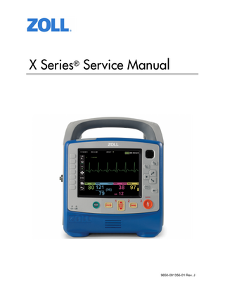
X Series® Service Manual
9650-001356-01 Rev. J
The issue date for the X Series Service Manual (REF 9650-001356-01 Rev. J) is April 2022. If more than 3 years have elapsed since the issue date, contact ZOLL Medical Corporation to determine if additional product information updates are available. Copyright © 2022 ZOLL Medical Corporation. All rights reserved. Rectilinear Biphasic, SurePower, X Series, and ZOLL are trademarks or registered trademarks of ZOLL Medical Corporation in the United States and/or other countries. Masimo and Rainbow are trademarks or registered trademarks of Masimo Corporation in the United States and/or other countries.
ZOLL Medical Corporation 269 Mill Road Chelmsford, MA USA 01824-4105 ZOLL International Holding B.V. Newtonweg 18 6662 PV ELST The Netherlands
0123
Table of Contents Preface
OVERVIEW ...1 SAFETY CONSIDERATIONS ...2 ADDITIONAL REFERENCE MATERIAL...2 CONVENTIONS ...3 SERVICE POLICY WARRANTY ...3 TECHNICAL SERVICE ...3 TECHNICAL SERVICE FOR INTERNATIONAL CUSTOMERS ...4 TAMPER PROOF LABELS ...4 SERVICE MANUAL FEEDBACK SURVEY ...4 Chapter 1
Maintenance Tests
X SERIES OVERVIEW ...5
Before You Begin the Maintenance Tests ...6 Equipment You Need to Perform the Maintenance Tests ...7 Required Accessories ...7
MAINTENANCE TESTS ...8
Physical Inspection of the Unit ...8 Leakage Current Test ...9 Treatment Report Test ...11 Readiness Test ...12 Operational Tests ...13 ECG Test ...19 Shock Test ...20 Synchronized Cardioversion Test ...22 Pacer Test (if applicable) ...23 SpO2 Test (if applicable) ...24 SpO2, SpCO, and SpMet Test (if applicable) ...25 EtCO2 Calibration ...26 EtCO2 Calibration Check ...27 EtCO2 Test ...28 IBP Test (if applicable) ...29 NIBP Calibration Check ...30 NIBP Leak Test ...32 Inflation/Deflation Test ...33 NIBP Functional Test ...34 Temperature Test (if applicable) ...35 Wi-Fi Test (optional) ...36 Audio Recording Test (if applicable) ...38 Real BVM Help Test (if applicable) ...39 CPR Feedback Test (if applicable) ...41 Paddles Test (if applicable) ...42
9650-001356-01 Rev. J
ZOLL X Series Service Manual
1
Chapter 2
Troubleshooting
OVERVIEW ...45 X SERIES ERROR MESSAGES ...45 Chapter 3
Disassembly Procedures
OVERVIEW ...57 REQUIRED EQUIPMENT ...57 SAFETY PRECAUTIONS...58 MODULES ...58 REMOVING THE HANDLE ...59 REMOVING THE PRINTER MODULE ...60 DISASSEMBLING THE MAIN UNIT ...62 REMOVING THE FRONT ENCLOSURE MODULE ...66 REMOVING THE DISPLAY MODULE ...68 REMOVING THE ETCO2 AND NIBP MODULES ...72 REMOVING THE MONITOR BOARD AND SPO2 MODULES ...76 REMOVING THE CP CARRIER MODULE ...82 REMOVING THE DEFIBRILLATOR BOARDS AND CAPACITOR BANK MODULES ...84 REMOVING THE AUX POWER CONNECTOR ...91 REMOVING THE DOCK CONNECTOR ...93 REPLACING THE MULTIFUNCTION CABLE GASKET ...95 Chapter 4
Replacement Parts
OVERVIEW ...97
Replacement Parts List ...98 Pictures and Diagrams ...103
Chapter 5
Functional Description
OVERVIEW ...119
Circuit Distribution ...119 Monitor Board ...119 Defibrillator Pacer Module ...122 Printer ...123 Lithium Ion Battery ...124
2
www.zoll.com
9650-001356-01 Rev. J
Chapter 6
Test After Repair
OVERVIEW ...125
Power Supply Test ...126
Appendix A
OVERVIEW ...129 X SERIES ELECTRICAL HARDWARE INTERCONNECT DIAGRAM ...130 X SERIES SIGNAL AND POWER INTERCONNECT SCHEMATIC ...131
9650-001356-01 Rev. J
ZOLL X Series Service Manual
3
Preface Overview The ZOLL® X Series™ Service Manual is intended for the trained biomedical equipment technician whose responsibility is to routinely inspect the device, identify malfunctions, andmake repairs at the subassembly level. This Service Manual has five main chapters and two appendices. Preface-Contains safety warnings and an overview of the manual’s contents. Be sure to review this section thoroughly before attempting to use or service the X Series unit. Chapter 1-Maintenance Tests describes step-by-step procedures for various maintenance tests. Chapter 2-Troubleshooting provides a listing of error messages to help the service technician detect faults and repair them. Chapter 3-Disassembly Procedures describes step-by-step procedures for disassembling modules in the X Series unit. Chapter 4-Replacement Parts List displays a complete list of ZOLL part numbers for field replaceable parts available for the X Series unit, allowing the service technician to identify and order replacement parts from ZOLL. Chapter 5-Functional Description provides technical descriptions for the X Series major subassembly modules. Chapter 6-Test After Repair provides information on what tests must be performed after making repairs to the device.
9650-001356-01 Rev. J
ZOLL X Series Service Manual
1
PREFACE Appendix A-X Series Electrical Hardware Interconnect Diagram and X Series Signal and Power Interconnect Schematic. Appendix B-Contains simulators and settings that may be used to assess the performance of the NIBP module. Maintenance Test Checklist-Contains a blank checklist that can be copied and used to record the results of device maintenance tests.
Safety Considerations The following section describes general warnings and safety considerations for operators and patients. Service technicians should review the safety considerations prior to servicing any equipment and read the manual carefully before attempting to disassemble the unit. Only qualified personnel should service the X Series unit. Federal (U.S.A.) law restricts this unit for use by or on the order of a physician. Safety and effectiveness data submitted by ZOLL Medical Corporation to the Food and Drug Administration (FDA) under section 510(K) of the Medical Device Act to obtain approval to market is based upon the use of ZOLL accessories such as disposable electrodes, patient cables and batteries. The use of external pacing/defibrillation electrodes and adapter units from sources other than ZOLL is not recommended. ZOLL makes no representations or warranties regarding the performance or effectiveness of its products when used in conjunction with pacing/defibrillation electrodes and adapter units from other sources. If unit failure is attributable to pacing/defibrillation electrodes or adapter units not manufactured by ZOLL, this may void ZOLL's warranty. Only qualified personnel should disassemble the X Series unit.
WARNING!
This unit can generate up to 2775 volts with sufficient current to cause lethal shocks. All persons near the equipment must be warned to “STAND CLEAR” prior to discharging the defibrillator. Do not discharge the unit’s internal defibrillator energy more than three times in one minute or damage to the unit may result. Do not discharge a battery pack except in a ZOLL SurePowerTM Charging Station. Do not use the X Series in the presence of flammable agents (such as gasoline), oxygen-rich atmospheres, or flammable anesthetics. Using the unit near the site of a gasoline spill may cause an explosion. Do not use the unit near or within puddles of water.
Additional Reference Material In addition to this guide, there is a X Series Operator’s Guide(REF: 9650-002355-01) which is a comprehensive reference work that describes all the user tasks needed to operate the X Series.
2
www.zoll.com
9650-001356-01 Rev. J
Conventions
Conventions WARNING! Warning statements describe conditions or actions that can result in personal injury or death.
Caution
Caution statements describe conditions or actions that can result in damage to the unit. Note:
Notes contain additional information on using the defibrillator.
Service Policy Warranty In North America: Consult your purchasing agreement for terms and conditions associated with your warranty. Outside of North America, consult a ZOLL authorized representative. In order to maintain this warranty, the instructions and procedures contained in this manual must be strictly followed. For additional information, please call the ZOLL Technical Service Department 1-800-348-9011 in North America.
Technical Service If the ZOLL X Series unit requires service, contact the ZOLL Technical Service Department: Telephone: 1-978-421-9655; 1-800-348-9011 Fax: 1-978-421-0010 Email: [email protected] Please have the following information readily available for the Technical Service representative: • Unit serial number
• Description of the problem
• Department where equipment is used
• Sample chart recorder strips or electronic log files documenting the problem (if applicable) • Purchase Order to allow tracking of loan equipmentPurchase Order for a unit with an
expired warranty
If the unit needs to be sent to ZOLL Medical Corporation, obtain a service request number (SR#) from the Technical Service representative. Return the unit in its original container to: ZOLL Medical Corporation 269 Mill Road Chelmsford, Massachusetts 01824-4105 Attn: Technical Service Department (SR#) Telephone: 1-800-348-9011; 1-978-421-9655 FAX: 978-421-0010
9650-001356-01 Rev. J
ZOLL X Series Service Manual
3
PREFACE
Technical Service for International Customers International customers should return the unit in its original container to the nearest authorized ZOLL Medical Corporation Service Center. To locate an authorized service center, contact the International Sales Department at ZOLL Medical at the above address.
Tamper Proof Labels
ZOLL products must be repaired by qualified individuals. The removal of the tamper proof label could result in voiding the factory warranty. Please contact the Technical Service Department if you have any questions or concerns prior to removing the label.
Service Manual Feedback Survey In an effort to continuously improve the efficacy of our product documentation, ZOLL Medical Corporation invites you to participate in a short survey regarding your experience using this manual. The responses collected from the survey will contribute directly to improving future revisions of this manual. Participation in the survey is voluntary and survey responses are made anonymous by default. If you would like to participate in the survey, please click or tap on the QR code below, or scan it with your mobile device. Alternatively, you may enter www.zoll.com/servicemanualsurvey into the address bar of your preferred web browser.
4
www.zoll.com
9650-001356-01 Rev. J
X Series Overview
Chapter 1 Maintenance Tests X Series Overview This chapter includes step by step instructions as part of an annual inspection procedure. These tests should be performed by trained biomedical professionals. Use the checklist at the back of this document (ZOLL X Series Maintenance Tests Checklist) to record your results of the maintenance tests. Additionally, it is necessary to perform the maintenance tests after repairs are made to the device to ensure that the functions of the X Series work properly and within specifications. See Chapter 6: Test After Repair for more information. This chapter describes the following maintenance tests: • 1.0 Physical Inspection of the Unit • 2.0 Leakage Current Test • 3.0 Treatment Report Test • 4.0 Readiness Test • 5.0 Operational Tests • 6.0 ECG Test • 7.0 Shock Test • 8.0 Synchronized Cardioversion Test • 9.0 Pacer Test (if applicable) • 10.0 SpO2 Test (if applicable) • 11.0 SpO2, SpCO, and SpMet Test (if applicable) • 12.0 EtCO2 Calibration • 13.0 EtCO2 Calibration Check • 14.0 EtCO2 Test • 15.0 IBP Test (if applicable) • 16.0 NIBP Calibration Check • 17.0 NIBP Leak Test • 18.0 Inflation/Deflation Test • 19.0 NIBP Functional Test • 20.0 Temperature Test (if applicable) • 21.0 Wi-Fi Test (optional) • 22.0 Audio Recording Test (if applicable) • 23.0 Real BVM Help Test (if applicable) • 24.0 CPR Feedback Test (if applicable) • 25.0 Paddles Test (if applicable)
9650-001356-01 Rev. J
ZOLL X Series Service Manual
5
Chapter 1
Maintenance Tests
Before You Begin the Maintenance Tests • Assemble the tools listed in following section. • Install a fully charged battery in the device. • Ensure the correct date and time are displayed on the device. • Perform the tests in the order presented. • Perform all the steps of each test procedure. • Complete all the steps of the procedure before evaluating the test results. • Review all caution and warning statements to ensure operator safety, especially
when discharging energy from the device.
• All tests should be completed within Manual mode operation. If the device starts in
AED mode, you must enter Manual mode operation before you begin each test.
6
www.zoll.com
9650-001356-01 Rev. J
X Series Overview
Equipment You Need to Perform the Maintenance Tests The equipment listed below is utilized in the maintenance test procedures in this chapter. Please note that not all simulators and analyzers will produce the same results. Be sure to follow the manufacturer’s recommendations for conducting the maintenance tests. Note: Some equipment may not be required based on device configuration. • Defibrillator analyzer • ECG simulator • IBP simulator with cable • Temperature simulator with cable • NIBP simulator • 5% CO2 calibration gas cylinder with CO2 sample line (AirGas P/N: Z03NI748BDC002)* • CO2 sampling line airway adapter (P/N: 8300-0520-01) • Stopwatch • Adult BVM • CPR Feedback Test equipment: •Universal Adapter Cable (ZOLL P/N: 8000-0804-01) with CPR Connector (P/ N: 8000-0370) Note: * ZOLL recommends purchasing the calibration gas and sample line kit listed above. If sourcing the calibration gas from a different source, ensure the calibration gas you use is medical grade, has a composition of 5% CO2, 21% O2 Balance N2, and has a flow rate of 0.5 liters per minute.
Required Accessories Note: Some accessories may not be required based on device configuration. • AccuVent cable and sensor • Auxiliary power source • Battery • Dual lumen NIBP hose • ECG cables • Microstream filterline (EtCO2) • Paddles • PC with Windows Media Player and speakers • Printer paper • SpO2 cable and sensor • USB thumb drive
9650-001356-01 Rev. J
ZOLL X Series Service Manual
7
Chapter 1
Maintenance Tests
Maintenance Tests 1.0 Physical Inspection of the Unit
Battery & Power
Cables
Main Housing
Observe this...
Pass / Fail
1.1 The device is clean and without any obvious signs of damage, cracks, loose housing parts, or excessive wear.
o o
1.2 The handle is secure and is in good condition.
o o
1.3 The printer door can open and close properly.
o o
1.4 The input connectors are clean and undamaged.
o o
1.5 The protective screen appears clean without significant scratches or cracks which could allow water ingress. Scratches to the device’s screen should not impede visibility of clinical data.
o o
1.6 The Multifunction Cable (MFC) gasket is in place and is intact. If replacement is needed, see Replacing the Multifunction Cable Gasket.
o o
1.7 All cables (including accessories) are free of cuts, cracks, and exposed wires.
o o
1.8 Ensure the device’s battery is properly secured within the battery well.
o o
1.9 On the rear case, inspect the AC power connector for signs of damage. Ensure the AC power cord is securely connected.
o o
1.10 Connect the device to AC power. Ensure the front panel AC and battery indicators are illuminated and not flashing.
o o
Note: If the battery indicator is not illuminated, ensure the battery is properly seated in the battery well and that the battery is not displaying a fault indicator. Inspect the pins and contacts both on the battery and within the battery well to ensure they are not damaged or in need of cleaning. The battery indicator will not illuminate unless the device is connected to AC power.
8
www.zoll.com
9650-001356-01 Rev. J
Maintenance Tests
2.0Leakage Current Test Before You Begin ZOLL X Series® and X Series® Advanced defibrillators have been certified as Class 1 ME externally powered per IEC/EN 60601-1 Standards. The device meets the Class 1 standard when operating on battery as the device is internally powered, and again when operating on AC due to the presence of a protective earth connection. The design of X Series and X Series Advanced devices complies with IEC standards, which allow for various methods of protection. Subclause 8.6 of IEC 60601-1 states the following: "Typically, metal ACCESSIBLE PARTS of CLASS I A1E EQUIPMENT are PROTECTIVELY EARTHED. However, they could be separated by other MEANS OF PROTECTION, in accordance with 8.5." Subclause 8.5.1 details the following example: "PATIENT CONNECTIONS and other ACCESSIBLE PARIS are separated from parts different from earth potential by DOUBLE or REINFORCED INSULATION" The X Series and X Series Advanced comply with subclause 8.5.1 as the external power supply is double insulated, and therefore provides protection to the entire rest of the system. Further, an isolation transformer within the external power supply also provides a reduction in voltage from the AC input to 14.5Vdc. The power supply itself remains Class 1 due to the presence of a protective earth; double insulation alone does not mandate that the adapter be classified as Class 2 by the IEC. Per the standards, a protective earth connection is not required to be carried through to the chassis. Any exposed metal components on the chassis, which carry through the power supply, are functional grounds only and are not to be considered protective. As the chassis does not require a protective earth due to the electrical system design, measuring protective Earth resistance is Not Applicable per the standard.
9650-001356-01 Rev. J
ZOLL X Series Service Manual
9
Chapter 1
Maintenance Tests
Equipment
See the manufacturer's instructions or supplied specifications for the leakage tester you use.
WARNING!
SHOCK HAZARD! Do not use anti-static robes, benches, floor mats, or perform the below tests at an ESD station during electrical safety testing. Follow all specified precautions offered by the ESA manufacturer.
WARNING!
Do NOT touch the DUT while the testing procedure is underway. Always consider the DUT to be electrified while testing is in progress.
Test Setup
See the manufacturer’s instructions or supplied specifications for the leakage tester you use. Perform the applied part leakage test with the following accessories: MFC, external paddles, and internal paddles. Perform these tests at the line-power voltage and frequency used in your installation. Functional Earth Locations: • Metal case of USB port • Rear case screws
Note: It is recommended to use the IEC 62353 standard for recurrent test and test after repair. IEC 62353 CLASS 1 LEAKAGE TEST LIMITS - DIRECT METHOD
Equipment Leakage (Direct) Applied Part Leakage (Direct)
BF*
CF**
500μA
500μA
BF*
CF**
5000μA
50μA
*Type BF: pads, paddles. **Type CF: ECG. Procedure
2.1
Verify that all electrical safety testing/ leakage measurements are within acceptable limits.
Pass/Fail
o o
Record your results on the Maintenance Test Checklist.
10
www.zoll.com
9650-001356-01 Rev. J
Maintenance Tests
3.0 Treatment Report Test Equipment
Printer paper
Test Setup
None Do this...
Observe this...
3.1
Power on the device and wait at least 30 seconds.
3.2
Using the quick access keys, select the code marker button.
Pass/Fail
R
3.3
Select a code marker from the list (for instance, O2) and then wait 20 seconds.
3.4
Select a different code marker from the list and then wait 20 seconds.
3.5
After 20 seconds, power off the device for 2 minutes. After 2 minutes, power on the device.
3.6
On the device, press the following quick access keys in the order presented: a) b)
LOG
c) 3.7
Using the navigation keys, select the second event in the list. A green check mark should appear next to the file.
3.8
Once the event is selected, select Print Treatment Summary.
On the printed treatment summary, observe that both code marker snapshots are present.
o o
Note: If any alarm conditions or recorder activated events occurred before this test, they will appear on the print out ahead of the code markers on the treatment summary report. This test has been placed at the beginning of the annual inspection procedure to eliminate unnecessary paper waste.
9650-001356-01 Rev. J
ZOLL X Series Service Manual
11
Chapter 1
Maintenance Tests
4.0 Readiness Test WARNING!
Take the necessary precautions to guard against shock or injury before you start conducting the defibrillator tests. Keep hands and all other objects clear of the Multi-Function Cable connections and any attached accessories when discharging the defibrillator. Before you discharge the defibrillator, warn everyone near the equipment to STAND CLEAR.
Equipment
Multi-Function Cable (MFC)
Test Setup
Press the Lead quick access key until Pads is the selected source. Connect the MFC to the device. Do this...
Observe this...
4.1
Connect the MFC to the test connector.
A SHORT DETECTED message appears on the display.
o o
4.2
On the device, set energy level to 30J.
4.3
On the device, press the CHARGE button to charge the device to 30J. Once the ready tone sounds, press the SHOCK button to deliver energy.
The message DEFIB SHORT TEST PASSED appears on the display.
o
o
o
o
Note:
Pass / Fail
This message displays briefly before disappearing.
The RFU Indicator shows a passing result (pictured here).
Note: For devices running software version 2.32.03 or higher, if the RFU Indicator shows a Do Not Use symbol, review the Readiness Test Log to identify any recorded faults. To access log, press the Setup quick access key > Device Info > Readiness Test Logs Review. 4.4
12
Unplug the MFC from the test connector.
The message CHECK PADS appears on the display.
www.zoll.com
o
o
9650-001356-01 Rev. J
Maintenance Tests
5.0 Operational Tests The X Series/X Series Advanced comes equipped with routine operational tests that can be performed periodically. These tests contain instructions within them that provide guidance during the tests. The operational tests on the device can be accessed by doing the following: 1. Turn on the device. 2. If the device is in AED mode, press the Manual quick access key to enter Manual Mode.
Press the More (
) and then the Setup (
) quick access keys.
3. Use the navigation keys to select Supervisor > Service > Device Tests. The operational tests
are displayed. Use the navigation keys to select one of the tests.
Note: You need a supervisor passcode to enter the Supervisor menu.
9650-001356-01 Rev. J
ZOLL X Series Service Manual
13
Chapter 1
Maintenance Tests 5.1 Keypad Test This test checks all the front panel buttons on the device to make sure they are working properly. Follow the on-screen instructions and use the navigation keys to move around the display and to make selections.
Note: To exit the screen after test is complete, press the Select button 3 times, and then use the navigation keys to highlight the return arrow in the bottom left corner. Select the arrow to return to the previous menu. 5.2 LED Test This test checks all the Light Emitting Diodes in the device to make sure they are working properly. Follow the on-screen instructions and use the navigation keys to move around the display and to make selections.
Note: The speed of the flash varies by color.
14
www.zoll.com
9650-001356-01 Rev. J
Maintenance Tests 5.3 LCD Test This test checks the colors of the Liquid Crystal Display on the device. Follow the on-screen instructions and use the navigation keys to move around the display and to make selections.
5.4 RFU Indicator Test This test checks the Ready For Use Indicator on the device to make sure it is working properly. Follow the on-screen instructions shown on the display.
9650-001356-01 Rev. J
ZOLL X Series Service Manual
15