User Manual
31 Pages
Preview
Page 1
P
H
A
R
M
A
C
I
A
B
I
O
T
E
C
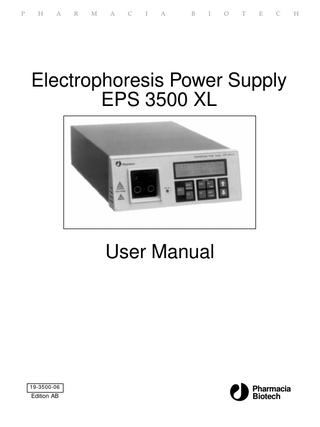
Electrophoresis Power Supply EPS 3500 XL
User Manual
19-3500-06
Edition AB
Pharmacia Biotech
H
Important user information Reading this entire manual is necessary for full understanding and safe use of this product. The exclamation mark within an equilateral triangle is intended to alert the user to the presence of important operating and maintenance instructions in the literature accompanying the instrument.
The lightning symbol within an equilateral triangle is intended to alert the user to the risk of exposure to high voltages. Should you have any comments on this manual, we will be pleased to receive them at: Pharmacia Biotech AB S-75182 Uppsala Sweden Pharmacia Biotech reserves the right to make changes in the specifications without prior notice.
Warranty and Liability Pharmacia Biotech AB guarantees that the product delivered has been thoroughly tested to ensure that it meets its published specifications. The warranty included in the conditions of delivery is valid only if the product has been installed and used according to the instructions supplied by Pharmacia Biotech AB. Pharmacia Biotech AB shall in no event be liable for incidental or consequential damages, including without limitation, lost profits, loss of income, loss of business opportunities, loss of use and other related exposures, however caused, arising from the faulty and incorrect use of the product.
Copyright© 1994 Pharmacia Biotech AB All rights reserved. No part of this publication may be reproduced, stored in a retrieval system or transmitted in any form by any means, without permission in written form from the company.
Contents 1. Introduction ... 3 2. Safety information ... 4 2.1 Safety precautions ... 4 2.2 In-built safety features ... 4 3. Unpacking and installation... 5 4. Technical description ... 6 4.1 Front panel ... 6 4.1.1 Display ... 6 4.1.2 Keyboard... 6 4.1.3 Output sockets ... 8 4.2 Rear panel ... 8 5. Operation ... 10 5.1 Overview ... 10 5.2 Programming a method ... 10 5.3 Editing a program ... 15 5.4 Running a program ... 16 5.5 Optional programming ... 19 5.6 Choosing run parameters ... 21 5.7 Short instructions ... 23 6. Maintenance ... 24 7. Trouble shooting ... 25 8. Technical specifications ... 26 9. Ordering information ... 28
1
1. Introduction
1. Introduction The Pharmacia Electrophoresis Power Supply EPS 3500 XL is a high quality, high precision and safe power supply for electrophoresis applications that require advanced programming and high voltage. EPS 3500 XL is primarily designed for techniques using programming in several phases and/or voltage gradients: ●
2-D (Two dimensional) electrophoresis using Immobiline®
●
IEF (Isoelectric focusing)
EPS 3500 XL is also suitable for: ●
DNA sequencing
●
SDS-PAGE (Polyacrylamide Gel Electrophoresis) Native PAGE
● ●
Agarose electrophoresis
●
Electroblotting DNA pulsed field electrophoresis
●
Nine programs each with up to nine phases can be saved. Limiting values for voltage, current and power as well as voltage gradients can be programmed for precise control of the electrophoresis. The EPS 3500 XL automatically switches over the controlling parameter according to programmed limits and gradients and conductivity variations in the system. Two electrophoresis units can be connected to the EPS 3500 XL and run with the same programmed method at one time.
3
2. Safety information
2. Safety information 2.1 Safety precautions
Extreme caution should be exercised in the operation of this instrument as it can develop sufficient voltage and current to produce a lethal shock. To avoid any risk of injury, the instrument should only be operated by properly trained personell and always in accordance with the instructions provided. Read this entire manual before using this power supply. 1. This instrument is designed for indoor use only. 2. The instrument must always be used with the protective earth lead of the power cord correctly grounded to earth at the mains outlet. 3. To permit sufficient cooling, ensure that the vents in the rear and sides of the instrument are not covered. 4. Do not operate the instrument in extreme humidity (above 95%). Avoid condensation by letting the unit equilibrate to ambient temperature when taking the power supply from a colder to a warmer environment. 5. Keep the instrument dry and clean. Wipe regularly with a soft damp cloth. Let the power supply dry completely before use. If wetted, unplug the power supply until the instrument is dry. 6. Use only undamaged electrical wire and equipment approved for the voltages you will use. High voltage wires must meet the requirements of the IEC 1010-2-031:1993 electrical standard. Any electrophoresis equipment connected to the power supply should meet the requirements of the IEC 1010-1:1993. 7. Note that the output is connected to the chassis/reference earth.
2.2 In-built safety features
The EPS 3500 XL is designed in accordance with the IEC 1010 (EN 60 1010-1 ) electrical safety standard. The power supply also has several builtin safety functions: 1. Functional earth leakage. Should the power supply be connected to an electrophoresis unit that has a leakage path to earth, the EPS 3500 XL will detect this fault and the high voltage is turned off. 2. Start current check. To ensure that an electrophoresis unit is connected correctly, the power supply checks that the resistance is not higher than a specified limit at a low safety voltage (<40 V). If this resistance is too high, the voltage is turned off. Too high a resistance can also be caused by using buffers with extremely low conductivity. The high voltage is also turned off in this case. This function can be disabled to perform certain applications (see 5.5 Optional programming). 3. Sudden load change detection. This function prevents accidents under running conditions due to a break in the electrical circuit such as a bad connection to the electrophoresis unit. The high voltage is turned off in such an event. Error messages are also shown on the display.
4
3. Unpacking and installation
3. Unpacking and installation Unpacking Check the contents against the packing list supplied. Inspect for any damage that may have occurred during transit. Report any damage immediately to your local Pharmacia Biotech representative and to the transport company concerned.
Mains connection Select the appropriate voltage range, 100-120 or 220-240 V, see Fig. 2. Warning!
If the power supply is connected to 220-240 V with the range set to 100-120 V, the instrument can be severely damaged.
Select the appropriate mains cable and connect one end to the mains socket on the EPS 3500 XL power supply, see Fig. 2, and the other end to an AC grounded outlet. Switch on the power. Each time the instrument is turned on a self diagnostic test is done. If an error is detected during the test a message will appear on the display and an alarm will sound.
Connection of the electrophoresis unit(s) Connect the leads from the electrophoresis unit (red to red, and black or blue to blue), see Fig. 1. The red lead is the positive and black or blue is the negative. Warning!
Use only undamaged electrical wire and equipment approved for the voltage you will use.
Two electrophoresis units can be run simultaneously with the same program. Please remember to double the limiting current and power if two electrophoresis units are run at the same time. The voltage will be the same regardless of the number of units.
Local regulation for Great Britain WARNING IMPORTANT This appliance must be earthed. The wires in the mains lead are coloured in accordance with the following code: Earth Green and yellow Neutral Blue Live Brown If the plug provided is unsuitable for your socket outlets, the plug must be cut off and suitable plug fitted. The cut-off plug should be disposed of and must not be inserted into any 13 amp socket as this can result in electric shock. The plug or adapter of the distribution panel should be provided with 13 amps fuse. As the colours of the wires in the mains lead of this appliance may not correspond with coloured markings identifying the terminals in your plug, proceed as follows: The green and yellow wire must be connected to the terminal in the plug which is marked with the letter E or by the earth symbol , or coloured green, or green and yellow. The blue wire must be connected to the terminal which is marked with the letter N or coloured black. The brown wire must be connected to the terminal which is marked with the letter L or coloured red. NOTE After replacing or changing a fuse, the fuse cover in the plug must be replaced with a fuse cover which corresponds to the colour of the insert in the base of the plug or the word that is embossed on the base of the plug, and the appliance must not be used without a fuse cover. Only 13 Amps fuse approved to B.S 1362 A.S.T.A. should be used. 5
4. Technical description
4. Technical description 4.1 Front panel
The front panel consists of an alphanumeric display, a keyboard with 9 membrane keys, a light emitting diode (LED) that lights when voltage is applied (HV on) and connectors for two electrophoresis units.
4.1.1 Display A 32 digit alphanumeric display guides you through the programming, shows current parameter values during the electrophoresis and final parameter values afterwards. It also asks questions and shows error messages. The display has an upper and lower row. Fig. 1 shows the display in the start position when power is switched on. The mode (in this case SET) is shown in the upper row on the left. The program number, the chosen way of controlling (step or gradient) and the phase number are shown in the center of the upper row. The program number shown is that of the previously entered program. The blinking figure, in this case “1”, indicates that it can be changed by using the
keys. The default way of controlling the power
supply is by step programming ( ). The upper right shows the programmed breakpoint for the actual phase. In this case it is 0:00h. The lower left, middle and right positions show voltage, current and power respectively, which all are zero for an unused program.
4.1.2 Keyboard
Fig. 1. The front panel of the EPS 3500 XL.
Set/enter set enter
6
Enters a value or choice, confirms this if valid, and moves programming to the next field. Valid values are voltage 35-3 500 V, current 1-150 mA, power 1-100 W, time 0:01-500 h, volthours 1-500 000 Vh, milliamperehours 1-25 000 mAh.
4. Technical description
In the RUN mode, pressing set
actual run. In addition,
enter
set enter
shows the programmed parameters for the
allows you to make changes in the program
during a run after first pressing
pause continue
. set
After a run, when in END mode, pressing
puts the instrument into
enter
SET, its programming mode.
Change up/Change down Changes the parameter, value or other choice in the field which is blinking. Numerical values are changed in an accelerating manner when a key is held down. Clicking a key changes the value in preset increments. Parameters or units (e.g. Vh) and choices (e.g. YES/NO) are changed with one key push. The keys can also be used to switch between time and volthours in RUN, PAUSE and END. The values scroll i.e. they automatically change from maximum to minimum value or vice versa.
run
Run run Pressing
starts the run and puts the program into RUN mode. The
current values for voltage, current and power are shown on the display. The elapsed time, volthours or milliamperehours are also displayed. Switch between these last three parameters with
pause continue
.
Pause Puts the instrument in PAUSE mode and switches off the voltage. The display shows the status of the run at the time the key was pressed. pause continue
only operates in RUN mode. Time, integrated voltage and integrated
current are retained. set
In the PAUSE mode,
enter
can be used to make changes in the program.
Return to RUN mode by pressing
STOP
pause continue
or by pressing
run
.
Stop Stops the run and puts the instrument in END mode. The voltage is switched off and the end parameters are displayed. Switch between time, integrated voltage and integrated current by pressing A run cannot be continued after pressing Press
run
STOP
.
. set
to run the same method again or press
enter
to choose
another program, program a new method or make changes in an existing method. 7
4. Technical description
Insert delete
Insert/delete Press
Insert
to insert or delete a phase in a program. This function is
delete
activated in SET mode. Note that a program must be completed by answering YES to the question “Last Phase?” in SET mode or by pressing exit
more
before you can use
Insert delete
.
More Places program in MORE mode. Gives access to some special functions. These include: COPY: Copying a program. CLEAR: Clearing a program SETUP: Disabling the start current check. MORE mode cannot be activated in RUN or PAUSE mode. Leave MORE by pressing
exit
exit
.
Exit Stops the execution of an operation, such as the entry of a value. Only values/units that have already been confirmed by when exit
exit
set enter
are retained
is pressed. Note that if a phase contains zeros when pressing
, that phase will be deleted.
Returns the instrument to the mode that was left or to the start position in SET.
4.1.3. Output sockets There are two sets of output sockets to allow two electrophoresis units to be connected and run at the same time, see Fig. 1. The voltage output is 0-3500 V. The negative output socket gives between 0 and -1750 V and the positive gives between 0 and +1750 V.
4.2 Rear panel
The rear panel is shown in Fig. 2. On the rear panel there is: 1. A mains switch. Press in I to switch on the power to the power supply. Press O to switch off the power. 2. A socket for the mains cable. 3. A switch for voltage range. The left position corresponds to 100-120 V and the right to 220-240 V. 4. Fan vents.
8
4. Technical description
Fig. 2. The rear panel of the EPS 3500 XL.
9
5. Operation
5. Operation 5.1 Overview
The main user operations of the EPS 3500 XL are: 1. Programming a method. 2. Editing a method. 3. Running a method. Programming, editing and running are discussed in more detail in the following three sections. Blinking characters are shown as bold characters.
5.2 Programming a method
Figure 3 summarizes this operation.
Start position When the power supply is switched on, the display shows the start position in SET mode. The previous program set is shown and that program number is blinking. If the power supply is switched on for the first time or if the program has been cleared, see section 5.5, the default way of controlling is step ( ),the breakpoint parameter is time (h), the alarm is off and the values are all zero.
SET: 0V
1 1 0mA
0:00h 0W
Choosing a program Up to nine programs, each with up to nine phases, can be entered. Press set enter
to confirm the program shown by the number on the display keys to choose another. Confirm with setenter .
or use
Choosing step or gradient programming Press
set enter
to confirm step( ) or use
keys to choose
set
gradient ( ).Confirm with enter Note that your choice of gradient or step programming applies for all phases within the program and you will only be asked to choose one of them when programming the first phase. Choosing step means that voltage, current and power limiting values are programmed. The electrophoresis will be controlled by one of these limiting values, which means that it is run at either constant voltage, current or power. The EPS 3500 XL automatically switches over the controlling parameter according to programmed limits and conductivity variations in the system. Thus the controlling parameter can switch within a phase. 10
1. Choose Program number (1 2)
Select by 2. Choose Step or Gradient mode. (Step)
1 Vh 5W
1 1 1 mA
SET: 500 V
Confirm by
set enter
SET: 2 1 STEP/gradient Select by
3. Confirm Phase number (1)
SET: 0V Confirm by
4. Set Voltage limit (step) or Voltage endpoint (gradient). (0 1000 V)
Confirm by
2 1 0 mA
0:00 h 0W
2 1 0 mA
0:00 h 0W
enter
set enter
SET: 0V
Confirm by
Select by 5. Set Current limit. (0 10mA)
set
2 1 10 mA
SET: 1000 V
set enter
0:00 h 0W set
Select by 6. Set Power limit. (0 10 W)
Confirm by
2 1 10 mA
SET: 1000 V
enter
0:00 h 0W set
Confirm by
Select by
1st Phase 7. Choose Breakpoint unit SET: (h, Vh, or mAh) or no 1000 V breakpoint (OFF). (h Vh) Select by (h OFF)
enter
Other phases 2 1 10 mA
0:00 h 10 W
Confirm by
set
Breakpoint OFF
enter
Vh 8. Set Breakpoint (0 1000 Vh)
2 1 10 mA
SET: 1000 V
Confirm by
Select by 9. Last Phase, Yes or NO?
0 Vh 10 W
SET: Last phase
enter
1000 Vh Y
2 1 ?
Confirm by
Select by
set
set enter
NO
YES 10. Choose Alarm OFF or ON (ON)
Alarm Phase 1? Phase:- - - -
Select by 11. The program is ready.
SET: 1000 V
N
Confirm by
2 1A 10 mA
set enter
1000 Vh 10 W
Fig. 3. Step-by-step summary of programming.
SET: 1000 V
2 1 10 mA
OFF 10 W 11
5. Operation
Table 1 and Fig. 4 illustrate a step program. The programming and running of this application are shown as Figs. 3 and 7.
3 500 Phase 4
Phase 3 2 000 1 500 Vh 1 000 Vh
Phase 1 1 000 500
Phase 2
1 000 Vh
120Vh 1
2 Time (h)
Fig. 4. Programming the voltage Iimiting profile in STEP mode. The parameters shown are the same as those listed in Table 1.
Table 1. The parameters of a step program. Phase Voltage number (V) 1 2 3 4
1 000 500 2 000 3 500
Current (mA)
Power (w)
Volthours (Vh)
10 10 20 30
10 5 15 25
1 000 120 1 000 1 500
Choosing gradient (/), means that a voltage endpoint for the actual phase is programmed together with current and power limiting values. A linear voltage gradient is made with zero (for the first phase) or the programmed endpoint of the phase before (for the next phases) as starting point and the programmed endpoint as endpoint. The electrophoresis will be controlled by this voltage gradient provided the limiting current or power is not attained. The EPS 3500 XL thus automatically switches over the controlling parameter according to the programmed limits and conductivity variations in the system. To illustrate voltage gradient programming, the programming for the IEF part of a 2-D electrophoresis with Immobiline DryStrip®is shown in Table 2 and Fig. 5. Note that the first phase is a very steep gradient to reach the 500 V start level (0 − 500 V, within 1 Vh). The next phase is actually a step since the endpoint for phase 2 is 500 V which is the same as the endpoint for phase 1. Phase 3 is the “real” gradient, the voltage is changed from 500 to 3 500 V in 5 hours. The last phase is a step again, the endpoint voltage is the same as for the phase before and the voltage will remain on 3 500 V for 9.5 hours. 12
Voltage (V)
5. Operation
3 500
3
4 Phase 4
33 250 Vh
Phase1 1 Vh
Phase 3
Phase 2 500 1
10 000 Vh
2
2 500 Vh 19.5
10
5
Time (h)
Fig. 5. Programming the voltage limiting profile in GRADIENT mode. The parameters shown are the same as those listed in Table 2. Table 2. The parameters of a gradient program. Phase Voltage number (V) 1 2 3 4
500 500 3 500 3 500
Current (mA)
Power (W)
Time (h)
Volthours (Vh)
1 1 1 1
5 5 5 5
0:01 * 5 5 9.5
1* 2 500 10 000 33 250
* The ramping from 0 to 500 V should be done as quickly as possible. The smallest possible time that can be set is 1 minute and the smallest possible Vh that can be set is 1 Vh. Vh was chosen for this program as breakpoint unit.
Choose phase number
set
Choose phase number with and confirm with enter . For a new program the default phase number is 1. If the first phase has been programmed and the question “Last phase ?” is answered by NO, the default number is 2 and so on.
Setting voltage, current and power The display will now flash for the set voltage limit (step mode) or voltage endpoint (gradient mode).Using the
keys, select the voltage set
limit or voltage endpoint desired for the run.Confirm with
enter
.
Repeat the same procedure for limiting current and limiting power. Programmable values for voltage are 35-3 500; current, 1-150 mA; power, 1-100 W.
Setting breakpoint Choose between automatic or manual break. For automatic break, choose breakpoint unit in either hours (h), volthours (Vh) or milliamperehours (mAh). 13
5. Operation
Select the correct unit or, for manual break, choose “OFF” with
.
set
Confirm with enter . Note that the breakpoint unit is valid for all phases within the program and you will only get this question when programming the first phase, see “Other phases” bypass in Fig. 3. If h, Vh or mAh is chosen, the display will flash for the break value for set
the actual phase. Set the value with
and confirm with
enter
.
Programmable values for time are 0:01-500 h, volthours, 1-500 000 Vh, milliamperehours, 1-25 000 mAh. If OFF is chosen, you have to break the electrophoresis manually by pressing
STOP
and only one phase can be entered. The program will go
back to the start position and the program number will flash.
Last Phase? After programming the breakpoint you are asked if this is the last phase or not. Select YES or NO with
and confirm with
set enter
.
If YES is selected, no more phases will be added and the alarm question will be shown, see below. If NO is selected, the next phase number for the program will be shown on the display together with zero values for all parameters. Program the next phase according to “Setting voltage, current and power” above and Fig. 3 point 4. Up to nine phases can be programmed.
Choosing alarm The alarm can be set separately for each phase. The following question is shown: Alarm Phase 1? Select YES or NO with and confirm with . If YES is selected in a 4 phase program this will be indicated by changing from - - - - to 1 - - - after “Phase:” on the lower row in the display. Then you will be asked about an alarm for the next phase. After answering YES or NO for the last phase, the start position in the SET mode will be shown. If alarm is selected for a phase a small “A” appears on the right of the phase number, i.e. 2 2A.
Back to start position The program is now back to the start position in the SET mode with the program number flashing. It is possible to go back to this position at any stage during programming in SET mode by pressing
exit
or
STOP
. Note
that the program is automatically saved with all choices that have been set
confirmed by
enter
when
exit
STOP
or
is pressed. If a phase containing
invalid values (zeros) is left, this phase will be deleted.
14
5. Operation
Disabling the start current check See Section 5.5 if you want to use this feature.
5.3 Editing a program
Changing a parameter value To change a parameter value, move to the start position in SET mode by pressing
exit
set
or
and choose program number as described on p. 10.
enter
If the programming mode (step or gradient) is changed it will be changed for all the phases within the program. Select phase number by
and move in the program with
to the value to be changed. Change with set enter
. Press
exit
set enter
and confirm with
.
Inserting and deleting a phase Inserting and deleting a phase is described schematically in Fig. 6. Note that you must first enter a phase before it can be inserted or deleted: 1.
If needed, change program number by entering the start position in exit
set
SET mode with
enter
and confirming by
or
set enter
, changing the number with . set
2. Bypass the mode question with
enter
.
3. Change to the desired phase number by
and confirm with
set enter
Choose to delete the phase shown on the display or insert a new phase with this phase number by pressing
and confirm with
set enter
.
If DELETE is chosen, the selected phase will be deleted and the program will move back to the position with the phase number blinking. Note that by deleting a phase, the numbers of the following phases will decrease by 1. If INSERT is chosen, the program will enter the same position and the new phase can be programmed as a new phase (see section 5.2 and Fig. 3, points 4−8). After entering the breakpoint, the question “Last Phase?” will be bypassed and the starting point for the next phase will be entered. Note that by inserting a new phase the number for the old phase with that number and the numbers for the following phases will increase by 1. Adding a phase after the last phase is done by entering the last phase as above, moving to the question “Last Phase?” and answering NO. The program will jump to the start position for programming a phase with the phase number blinking. Proceed with programming as described for a new program. It is not possible to insert or delete a phase for a running program.
15
.
5. Operation
1. Choose Program Number (1 2)
SET: 500 V
1 1A 1 mA
set
Select by 2. Confirm Step or Gradient. (Step)
1 Vh 5W Confirm by
enter
SET: 2 1 step/GRADIENT set
Confirm by 3. Choose Phase number (2) and enter INSERT/DELETE
SET: 1000 V
enter
2 1 120 mA
Select by 4. Choose INSERT or DELETE
1000 Vh 10 W
Enter by
Insert INS/del
Confirm by
INSERT SET: 0V
2 2 0 mA
delete
Phase 2
Select by
5. Program a new phase 2.
Insert
set enter
DELETE 00:00 h 0W
SET: 2000 V
2 2 20 mA
1000 Vh 15 W
Programming point 4
5. Back to new Phase 2 start position. Old Phase 2 deleted.
Fig. 6. Inserting and deleting a phase in a program.
Editing a running program See section 5.4
Copying and clearing a program See section 5.5.
5.4 Running a program
Connect the leads from the electrophoresis unit (red to red, and black or blue to blue). Red is positive and black or blue negative. UP to two electrophoresis units can run at the same voltage at one time. Please remember to double the maximum current and power conditions if two units are to be run. Voltage will be the same regardless of the number of units. The current should also be doubled if two gels are run on the same unit. Running a program is described schematically in Fig. 7.
Choosing a program Press
set enter
and select the program you wish to run by pressing
until the value is correct. (Omit this step if you have just programmed or edited a method as described in sections 5.2 and 5.3.) 16
5. Operation
1. Choose Program Number. (1
2)
SET: 500 V
1 Vh 5W
1 1 1 mA
Select by 2. Start the run.
2 1A 1000 Vh SET: 1000 V 10 mA 10 W run
Start by
RUN: 500 V
2 1A 10 mA
5 Vh 5W
set
pause
enter
SET: 1000 V
continue
RUN: 900 V
2 1A 1000 Vh 10 mA 10 W
2 1A 1000 Vh 10 mA 9 W
exit
PAUSE: 900 V pause
or wait 5 s
2 1A 1000 Vh 10 mA 9 W
run
continue
or
3. During a run you can view the settings.It is also possible to interrupt the run and make changes in the program.
set
pause
enter
P-SET: 1000 V
continue
or
exit
2 1A 1000 Vh 10 mA 10 W
Programming STOP
4. Stop the run manually
5. The run is stopped automatically.
RUN: 2500 V
2 4A 880 Vh 10 mA 25 W
END: 3125 V
2 4A 3620 Vh 8 mA 25 W
END: 2500 V
2 4A 3000 Vh 10 mA 25 W
Fig. 7. Running, viewing and pausing a program.
Running Press
run
to start the electrophoresis. Information about the status of the
start current check will be displayed for a few seconds. The display will then show current values for voltage, current and power and one of elapsed time, volthours or milliamperehours. You can switch between showing the elapsed time, volthours or milliamperehours by
.
The parameter controlling the electrophoresis is underlined. A light emitting diode shows when voltage is applied (HV on). If no current is displayed or if “HALT: Low start current” is shown, please check the electrical connections to the electrophoresis equipment.
Pausing You can interrupt the electrophoresis for sample loading and/or changing the program by pressing
pause continue
. Voltage will no longer be supplied, the 17
5. Operation
“HV on” LED goes off, and you may safely load your samples. pause
The display shows the status of the run when continue was pressed. Switch between time, integrated voltage and integrated current for the phase pause
running when continue was pressed with
. pause
When sample loading is complete, press either
continue
again or
run
to
continue the run from where it was interrupted. Editing a running program when in PAUSE set
When in the PAUSE mode you can also press
to make
enter
changes in the program. This mode is called the P-SET mode. When the P-SET mode is entered you can make changes as described in the editing section (5.3, Changing a parameter value). It is not possible to insert or delete a phase for a running program. The P-SET mode is the same as the SET mode apart from restrictions in setting the breakpoint. Naturally, it is not possible to enter a time, integrated voltage or current that is already passed. Press run
exit
or
pause
or pause
continue
to go back from P-SET to PAUSE. Press
to proceed with the electrophoresis.
continue
View programmed values It is also possible to view the programmed values during a run by pressing set enter
. Note that no values can be changed here. Only one phase is
shown at one time. Switch to another phase by using
. The
display returns automatically to show RUN values after 5s. Alternatively use exit
or
run
.
Stopping the run and viewing end parameter values When the programmed time, volthours or milliamperehours for the last phase is attained, the program will enter the END mode. It is also possible to break the run manually by pressing
STOP
.
In both cases, the voltage, current and power will go to zero as indicated by the “HV on” LED switching off. The end parameter values are displayed. Switch between total elapsed time, integrated voltage or integrated current for all phases in the program by
.
An alarm will sound at the end of each phase if selected in the program. You can stop the alarm after the last phase by pressing A run cannot be continued after pressing
STOP
STOP
.
.
Disconnect the leads and proceed with post-electrophoretic techniques. 18
5. Operation
Since diffusion will begin as soon as voltage is turned off, you should remove the gel and begin staining, blotting or autoradiography immediately. Some special functions are placed in MORE. These are:
5.5 Optional programming
COPY: Copying a program. CLEAR: Clearing a program. SETUP: Disabling the current check. The MORE mode is described in Fig. 8.
1. Enter MORE
SET: 500 V
more
Select MORE by 2. Choose COPY or CLEAR a program or choose SETUP for disabling the start current check.
1 Vh 5W
1 1 1 mA
MORE: SETUP copy/clear/SETUP Selected by set
Confirm with
COPY 3. Choose Program to copy from. (1 1)
3. Choose Program (1 8)
COPY: P1 P? Used: P12--56-89
enter
SETUP: Select program
Selected by Confirm with
enter
4. Choose Program destination (3 4)
Prog.
Selected by
set
Confirm with
enter
4. Choose start current check YES or NO
P8
Cleared
Current check at start? YES/no
Wait 2s
set
Confirm with
enter
4. Message
COPY: P1 P3 Free: P--34--7--
P1
Selected by set
set
Confirm with
3. Choose Program (1 2)
CLEAR
CLEAR: Program 1 Used: P12--56789
Selected by
SETUP
enter
Selected by Confirm and Exit by
set enter
5. Message
Prog. P1 copied to P4 Wait 2s 6. Back to SET mode
SET: 500 V
1 1 1 mA
1 Vh 5W
Fig. 8. Optional programming in MORE mode
19