Schmitz
Examination and Treatment Chairs
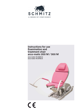
Arco-matic 200M-300M Examination and Treatment Chair Instructions for Use May 2018
Instructions for Use
88 Pages
Preview
Page 1
Instructions for use Examination and treatment chair arco-matic 200 M / 300 M arco-matic 114.9600.0 arco-matic 114.9700.0
Table of contents These instructions for use ... 4 General ... 4 Warnings ... 4 Text symbols... 4 Important safety information ... 5 Regulatory ... 6 Product classification ... 6 Intended use ... 6 Approved accessories ... 7 Device description... 9 Diagram ... 9 Features ...11 Control units... 12 Delivery ...13 Storing the product ... 13 Transport to destination ... 14 Unpacking... 14 Transport at destination ... 15 Setup ...16 Preparation for operation... 17 Levelling ... 17 Setting up a hardwired connection (optional) ... 18 Fitting the back foot section cover ... 20 Connecting the foot control unit ... 23 Fitting the front foot section cover... 24 Connecting the hand control unit ... 25 Connecting ... 26 Mains connection ... 26 Potential equalisation (optional, 101.0481.0) ... 26 Sockets on the device (optional, 101.0482.0) ... 27 Positioning patients ... 29 Operation ... 30 Safety information ... 30 Switching on / off ... 31 Hand control unit ... 32 Foot control unit ... 37 Standard accessories... 39 Back pad ... 39 Seat pad ... 40 Head pad ... 41 Rinsing basin... 42 Cradle of the hand control unit ... 43 Side rail accessories ... 44 Arm rest (101.0019.0) ... 44 Göpel leg support (101.0459.0), attachment clamp (101.1670.0) ... 45 Other optional accessories ... 49 Foot supports (101.0492.0) ... 49 Protective cover for foot supports (101.0475.0) ... 50 Göpel leg support (101.0493.0) ... 51 Head cushion (101.0472.0) ... 53 Mobility (101.0466.0) ... 54 Foot rest for the doctor (right: 01.0468.0, left: 101.0469.0) ... 56 Leg plate (101.0471.0) ... 57 Paper roll (101.0489.0) ... 58 Rinsing basin with convenient holder (101.0495.0) ... 59 Colposcope support (101.0467.0) ... 60 Potential equalisation (101.0481.0) ... 61 Cleaning and disinfecting ... 62 Pads ... 63 Stainless steel parts... 64 Rinsing basin... 64 2
Instructions for use arco-matic 200 M / 300 M - Version 2018-05-08 GBR ID no. 2038823A
Replacing fuses ... 65 Technical Service ... 66 Wear parts ... 67 Visual and functional checks ... 67 Disposal ... 69 Product identification ... 70 Identification plate ... 70 Symbols used ... 71 Technical data ... 73 Connection dimensions ... 76 EMC declaration ... 77 EC Declaration of Conformity (including accessories) ... 79 Glossary ... 82 Index ... 84 Contact information ... 88
Instructions for use arco-matic 200 M / 300 M - Version 2018-05-08 GBR ID no. 2038823A
3
These instructions for use General These instructions for use reflect the state of knowledge at the time of printing and make no claim to completeness. The information provided in these instructions for use may be outdated due to the ongoing technical development of our products. However, all information is regularly updated in revisions. Illustrations in these instructions for use are not necessarily to scale. Keep these instructions for use at the place of use of the product.
These instructions for use must be read and observed by all persons who use, operate or clean the product. To be able to use the described product safely, the provisions of these instructions for use must be observed. Please observe in particular warnings, ambient conditions, installation instructions, operating instructions, inspection and maintenance regulations, as well as the standards listed in these instructions for use.
Warnings A risk assessment pursuant to ISO 14971:2007+ amendment:2009 (Risk management for medical devices) was performed for this device. The signal words, symbols and colours of the warnings were selected in accordance with ANSI 535.6. The warnings were scaled in accordance with the following definitions for risk assessment.
DANGER! “DANGER” refers to a hazardous situation which could result in serious injury or death if it is not avoided. Serious injuries are irreversible injuries requiring permanent and regular medical care.
WARNING! “WARNING” refers to a hazardous situation which could result in moderate to serious injury if it is not avoided. This includes reversible injuries requiring care or examination by a medical professional.
CAUTION! “CAUTION” refers to a hazardous situation which could result in slight to moderate injury if it is not avoided. This includes reversible injuries not requiring medical care.
NOTE “NOTE” refers to information not relating to personal injury, e.g. information relating to damage to property.
RECOMMENDATION Recommendations are information that helps readers use the product better, longer and more safely.
Text symbols A triangle before the text means: Execute this work step. Execute this partial work step. A square before the text means: This is the result of the previous action. A bullet point before the text means: • This is part of an itemisation.
4
Instructions for use arco-matic 200 M / 300 M - Version 2018-05-08 GBR ID no. 2038823A
Important safety information Use of the product This product is state-of-the-art and was built according to recognised safety rules. Nevertheless, risks to the life and limb of users or third parties may occur, or this product and other assets may be adversely affected by the use of this product. This product must only be used in sound condition and for its intended use. Suitability for use in oxygenated atmosphere The examination chair must not be operated in an oxygenated atmosphere. Technical changes It is not permitted to modify the examination and treatment chair without the consent of the manufacturer. Attaching accessories When mounting accessories, always check the condition of the accessory, and make sure that it is attached securely. Replacement parts Replacement parts have to meet the requirements established by SCHMITZ u. Söhne. Using original replacement parts guarantees at all times that the parts comply with requirements.
Mandatory training This product may only be operated by persons instructed in its proper use. Patient positioning The user must be familiar with and must comply with the applicable organisational and national rules and regulations for the proper positioning of patients. The nursing staff are responsible for ensuring that the patients are positioned in such a way that no threats are posed to respiration, the nervous system or the circulatory system. This applies in particular to anaesthetised or unconscious patients. HF devices Combination with HF or defibrillator devices is possible. Please note that the patient must be insulated from the examination and treatment chair. Use electrically insulated underlays between the patient and the examination and treatment chair. To this end, the instructions for use issued by the device manufacturer must be complied with. Checklist Perform a visual and functional check regularly according to the device-specific checklist provided in these instructions for use.
Non-slip setup Before and during use of the product, it must be ensured that the product has sufficient floor adhesion and that there is good slip resistance for both product and user.
Instructions for use arco-matic 200 M / 300 M - Version 2018-05-08 GBR ID no. 2038823A
5
Regulatory Product classification In combination with the accessories listed in “Tab. 1” on page 8, the product is a Class I medical device according to Annex IX of the Medical Device Directive 93/42/EEC. Harmonised standards were used to assess compliance. The product meets the
fundamental requirements according to Annex I of Directive 93/42/EEC, as well as of amending Council Directive 2007/47/EC regarding medical devices (Medical Device Directive).
Intended use Only uses that are listed in this “Intended use” chapter are intended for the purposes of IEC 606011:2005 + amendment: 2006 + amendment: 2007 + supplement1:2012. Any other use will result in an exclusion of liability. The examination and treatment chair arco-matic is intended for use in human medicine only. The examination and treatment chair may be used for the following purposes: • for the short-term positioning of patients for urological examinations and treatment of non-anaesthetised or sedated persons. A person placed under the care of a guardian may only be positioned on the examination chairs under supervision. Under these same conditions, the examination chair can also be used in gynaecology and proctology. The examination and treatment chair may not be used: • as an operating table, • for transporting patients.
6
The safe working load of the examination and treatment chair as per IEC 60601-1:2005 + amendment:2006 + amendment:2007 + supplement 1:2012 is 250 kg less the weight of the attached accessories. It may only be used in Group 0 and Group 1 medical rooms according to and/or IEC 60364-7-710:2002-11. Permissible user groups for the product are: • Trained medical personnel (doctor/nurse) • Trained cleaning staff • Hospital technicians
Instructions for use arco-matic 200 M / 300 M - Version 2018-05-08 GBR ID no. 2038823A
Approved accessories Accessories from SCHMITZ u. Söhne were developed for and tailored to this product (for a list of accessories, see the table below). Third-party accessories must be inspected and used with reference to their instructions for use. (*) The corresponding weight of the patient is indicated in brackets. Example: a safe working load of ‘‘60 (250) kg’’ means that the accessory can support a weight of up to 60 kg. The part of the body that weighs 60 kg indicates a total body weight of 250 kg.
Fig. 1 Notes regarding the following table (sample values) Article no.
Description
Safe working load as per IEC 606011:2005, (*) in kg:
Net weight per unit in kg:
101.0492.0
Foot supports for positioning the patient’s legs.
25
4
101.0464.0
Side rails for seat section (pair), 150 mm long, used to attach side rail accessories
25
0.3
101.0466.0
Integrated double castor (set) for the examination and treatment chair (‘‘mobility’’). Serves to transport the examination and treatment chair without a patient.
250
5
101.0472.0
Magnetic head cushion for positioning the patient’s head.
/
0.51
101.0474.0
Leatherette cover (pair) to improve the grip on the Göpel leg support
/
0.2
101.0475.0
Protective covers (pair), to protect the foot supports when used with shoes.
/
0.1
101.0482.0
2 sockets as power supply for accessories attached to the examination and treatment chair, such as colposcopes or examination lights
/
/
101.0487.0
LED illumination
/
/
101.0493.0
Göpel leg support with integrated handle, for positioning the patient’s legs during examination and treatment.
25
6
101.0471.0
Extensible leg plate to position the patient’s legs
50
3
101.0467.0
Colposcope support (attachable on both sides) for mounting colposcopes.
25
7
101.0473.0
Leatherette cover (pair) to improve the grip on the foot support
/
0.2
101.0478.0
Foot supports, short (version), for positioning the patient’s legs during examination and treatment
25
4
101.0481.0
Potential equalisation to reduce the patient leakage current
/
/
101.0483.0
2 sockets for the Swiss market as power supply for accessories attached to the examination and treatment chair, such as colposcopes or examination lights
/
/
101.0489.0
Paper roll, 500 mm wide, as hygienic cover for the pads. /
1.5
101.0019.0
Arm rest, serves to stabilise the patient’s arm
20
6.8
101.1670.0
Attachment clamp (piece) for mounting approved accessories on the side rails.
25
0.7
101.0459.0
Göpel leg support for positioning the patient’s legs during examination and treatment
see ‘‘Safe working load’’ on page 45
4
Instructions for use arco-matic 200 M / 300 M - Version 2018-05-08 GBR ID no. 2038823A
7
Article no.
Description
Safe working load as per IEC 606011:2005, (*) in kg:
Net weight per unit:
101.0463.0
Side rails for seat section (pair), 290 mm long, for mounting side rail accessories
25
0.6
101.0468.0
Foot rest for the doctor, to support the doctor’s feet during the examination (right-sided version).
25
1.5
101.0469.0
Foot rest for the doctor, to support the doctor’s feet during the examination (left-sided version).
25
1.5
101.0476.0
Protective cover for seat pad to protect the seat pad
/
0.2
101.0465.0
Side rails for the back section for mounting accessories on the back section
20
1
Tab. 1 Approved accessories from SCHMITZ u. Söhne GmbH & Co. KG
8
Instructions for use arco-matic 200 M / 300 M - Version 2018-05-08 GBR ID no. 2038823A
Device description Diagram
Fig. 2 Examination and treatment chair arco-matic 200 M / 300 M
Head pad
Head cushion (optional, 101.0472.0)
Back pad
Leatherette cladding
Seat pad
Lifting arm
Rear foot section cladding
Foot supports
Rinsing basin
Foot control unit (e.g. arco 200 M)
Hand control unit
Front foot section cladding
Tab. 2 Position numbers of the above illustration
Instructions for use arco-matic 200 M / 300 M - Version 2018-05-08 GBR ID no. 2038823A
9
Fig. 3 Examination and treatment chair arco-matic 200 M / 300 M (back)
Locking pedal (optional)
On/off switch
Fine-wire fuses of the integrated sockets
Attachment screws for the rear foot section cladding Integrated socket (optional, 101.0482.0)
Screw thread for the attachment screws
Cable brackets
Mains connection
Potential equalisation (optional, 101.0481.0)
Tab. 3 Position numbers of the above illustration
10
Instructions for use arco-matic 200 M / 300 M - Version 2018-05-08 GBR ID no. 2038823A
Features arco-matic 200 M / 300 M is an adjustable examination and treatment chair for use in gynaecology. Operation The examination and treatment chair can be adjusted with a foot control or hand control. Four memory buttons are available for this purpose, with which the positions of all available adjustment features can be saved. For version-specific features, see Tab. 4. Accessories The integrated double castors (article number 101.0466.0, optional) can be locked or set to a drive mode for “quick forward drive/rotation on its axis” or “easy mobility in all directions”.
The head cushion (article number 101.0472.0, optional) is fixed to the head pad magnetically. It can be adjusted by 560 mm in a longitudinal direction and 250 mm in a transverse direction. During the adjustment of the examination and treatment chair, the rinsing basin remains in a horizontal position automatically. It measures 325 mm × 175 mm (depth: 65 mm) and can be removed. Paper rolls with a width of 400 mm and 500 mm can be inserted. The diameter of these paper rolls may not exceed 140 mm. The mount for the paper roll is enclosed on all sides and thus protected against dirt. Some models feature LED lighting. This LED lighting comes on as soon as the examination and treatment chair is connected to the mains and switched on. If the LED lighting is not required, it can be switched off by a maintenance engineer.
Feature
arco-matic 200 M
arco-matic 300 M
Seat height adjustment
present
present
Back section adjustment
present
present
Foot support adjustment
not present
present
Number of storable memory positions
4
4
Tab. 4 Version-related features of the examination and treatment chair
Instructions for use arco-matic 200 M / 300 M - Version 2018-05-08 GBR ID no. 2038823A
11
Control units The examination and treatment chair is operated using a hand control unit or a foot control unit. The control unit of the examination and treatment chair is equipped with a memory for four adjustable chair positions (“memory function”). Adjustment functions operated by electric motors are activated by a foot control unit or hand control unit. For more information on the hand control unit, please see chapter “Hand control unit” on page 32. For more information on the foot control unit, please see chapter “Foot control unit” on page 37.
Fig. 4 Control units of the arco-matic 200 M
Fig. 5 Control units of the arco-matic 300 M
12
Instructions for use arco-matic 200 M / 300 M - Version 2018-05-08 GBR ID no. 2038823A
Delivery The product is generally stored prior to the shipping and transport of the product to the end user, and the unpacking of the delivered product at the end user’s premises, by SCHMITZ u. Söhne and/or its distribution partners.
This chapter is intended for those people who handle the storage of the product prior to the shipping, the transport of the product at the end user’s premises and the unpacking of the supplied product at the end user’s premises.
Storing the product
NOTE If ambient conditions deviate from the range of values stated in Tab. 5, the electronic control unit may be damaged irreparably during storage or transport. Hence, the examination and treatment chair must not be exposed to conditions other than those indicated during transport and storage.
During transport to the place of destination and during storage, specific requirements apply for the ambient conditions. These requirements may deviate from the ambient conditions required during operation. The admissible ambient conditions during transport to the destination and during storage are indicated by symbols on the packaging.
For the ambient conditions permitted for storage and transportation, please see Tab. 5. Parameter Range of values
Ambient temperature -10°C – +50°C
Relative humidity 20% – 95% at 30°C non-condensing
Air pressure 700 – 1,060 hPa
Symbol on the packaging
Tab. 5 Ambient conditions permitted during storage and transport
Instructions for use arco-matic 200 M / 300 M - Version 2018-05-08 GBR ID no. 2038823A
13
Transport to destination The products from SCHMITZ u. Söhne are prepared for transportation when they leave the plant. After delivery, transport the product to its place of use in its original packaging!
Unpacking
NOTE The pads of the examination and treatment chair can easily be slit when cutting open the packaging film.
The product must be unpacked at its place of use. Inspect the product during unpacking. Any damage incurred during transportation must be reported immediately to the applicable partner or SCHMITZ u. Söhne.
14
Instructions for use arco-matic 200 M / 300 M - Version 2018-05-08 GBR ID no. 2038823A
Transport at destination To lift the examination and treatment chair, e.g. from a pallet, the cladding must first be removed from both foot sections. The chair must be lifted with carry straps (included in the delivery).
The following steps must be followed even if, at a later stage (e.g. after final use), the examination and treatment chair is to be moved and the chair is not equipped with a mobility function.
Attaching the carry straps The examination and treatment chair comes with foot supports, which are fitted as shown in Fig. 6. The foot supports are fitted the other way round for delivery: the right foot support is on the left side and vice versa. The foot supports must be removed before the examination and treatment chair is transported at the destination. Remove the attached foot supports. Keep the right and left foot supports separately. Each is to be fitted on the other side respectively once the examination and treatment chair has been set up (see “Setup” on page 16).
Fig. 6 Foot support, before assembly 1) Foot support Attach two carry straps each on the left and right side as shown in Fig. 7 or in Fig. 8. Lower the examination and treatment chair from the pallet. This must be done by four people.
NOTE The examination and treatment chair will be damaged if it is lifted by the back pad and seat pad. The examination and treatment chair must therefore always be lifted by the foot section.
Moving at the destination Models with a mobility function can also be transported at the destination by moving the examination and treatment chair along to the desired location. Please refer to the instructions in chapter “Mobility (101.0466.0)” on page 54.
Fig. 7 Attaching carry straps (for non-mobile models) 1) Carry strap
Fig. 8 Attaching carry straps (for mobile models)
Instructions for use arco-matic 200 M / 300 M - Version 2018-05-08 GBR ID no. 2038823A
15
Carrying
WARNING! Components such as the foot rest or colposcopes are not designed as carrying or lifting handles. When subjected to such a load, the component will detach from the examination chair. Serious injury may occur when the examination chair falls as a result. Components such as the foot rest or colposcopes are not designed as carrying or lifting handles!
To carry the product after unpacking or final use, it must be brought into the transport position.
The transport position is the position in which the product was delivered: • disconnected from the power supply, • no mounted accessories, • product moved down (height adjustment set to lowest level). Bring the product into the transport position. Disconnect the mains connection (disconnect the mains plug). Detach mounted accessories. Move the product to its lowest position. During transportation, ensure that the unit does not collide with persons or objects.
Setup
NOTE The examination and treatment chair requires some time to acclimatise. If the acclimatisation period is too short, the examination and treatment chair may be damaged. For this reason, please let the examination and treatment chair acclimate for at least 12 hours after every transport.
Set up the unit so as to ensure that • the product can be used and operated without any obstruction, • the mains plug is easily accessible, • the displays can be read easily, and • that existing switches can be operated easily (e.g. the on/off switch at the rear must be easily accessible). Fit the removed foot supports (see “Attaching the carry straps” on page 15) to the opposite side to which they were previously fitted.
NOTE The power cord and supply cable for the foot control unit may be damaged if the levelling screws touch down on them. For this reason, always make sure that none of the electric cables are pinched under the levelling screws or under the foot section.
16
Instructions for use arco-matic 200 M / 300 M - Version 2018-05-08 GBR ID no. 2038823A
Preparation for operation Final mechanical works on the product are generally performed by SCHMITZ u. Söhne or its distribution partners. In so doing, the examination and treatment chair must be levelled out, the foot section cladding must be attached and the cradle of the hand control unit must be mounted. This chapter is intended for people who deal with the final mechanical works on the products.
The final mechanical works may be performed only by personnel trained and authorised by SCHMITZ u. Söhne or its distribution partners. Performing the works described in this chapter requires a spirit level, an M3 hexagon spanner, a Phillips screwdriver, an M2.5 hexagon spanner and a bar.
Levelling The levelling feet serve to compensate for uneven floors and to ensure that the examination and treatment chair is placed in a horizontal position. Lift the examination and treatment chair on one side. Secure the examination and treatment chair by placing a bar under the foot section. Turn the levelling foot in or out. Remove the bar and lower the examination and treatment chair. Check to see if the examination and treatment chair stands properly. Repeat until the examination and treatment chair stands properly.
NOTE The power cord and supply cable for the foot control unit may be damaged if the levelling screws touch down on them. For this reason, always make sure that none of the electric cables are pinched under the levelling screws or under the foot section.
Fig. 9 Lifting the examination and treatment chair 1) Front levelling foot (octagonal)
Fig. 10 Lifting the examination and treatment chair 1) Rear levelling foot
Instructions for use arco-matic 200 M / 300 M - Version 2018-05-08 GBR ID no. 2038823A
17
Setting up a hardwired connection (optional) The examination and treatment chair can, if necessary, be hardwired on-site instead of connected to the mains supply via the mains cable. This requires some adjustments to be made in the control unit housing.
DANGER! Risk of electric shock! Improper electrical work to the examination and treatment chair puts patients, medical personnel and those carrying out the work at risk! The modifications listed in this chapter must, therefore, only be carried out by qualified specialist personnel! The examination and treatment chair must be completely disconnected from the mains supply during such work!
Fig. 11 Remove the cover of the control unit housing
If setting up an electrical hardwired connection for the examination and treatment chair, a wall switch must be installed, which can switch the examination and treatment chair off. Disconnect the mains plug of the examination chair. Undo and remove the attachment screws on the cover of the control unit housing as shown in Fig. 11. Remove the cover of the control unit housing as shown in Fig. 12.
Undo the screw from the mains socket. Undo the conductors of the mains cable on the mains adapter. Undo the mains cable attachment screw (Fig. 13, Pos. 5).
Fig. 12 Remove the cover
Fig. 13 Inside of the mains socket 1) Green and yellow protective earth conductor 2) Brown conductor 3) Blue conductor 4) Cable attachment screws 5) Mains cable attachment screw
18
Instructions for use arco-matic 200 M / 300 M - Version 2018-05-08 GBR ID no. 2038823A
Disconnect the mains cable from the control unit housing.
Fig. 14 Disconnect the mains plug 1) Screw connection 2) Mains plug Feed the mains cable of the on-site electrical connection through the opening in the control unit housing as shown in Fig. 15. Connect the conductors of the new mains cable to the mains socket as shown in Fig. 13. Put the cover back on the mains socket and screw on. Replace the cover of the control unit housing. Secure the cover of the control unit housing again with attachment screws.
Fig. 15 Feed the mains cable through the opening 1) Mains socket 2) Mains cable
Instructions for use arco-matic 200 M / 300 M - Version 2018-05-08 GBR ID no. 2038823A
19
Fitting the back foot section cover If the product is equipped with mounted double castors, the rear foot section cladding is already mounted. If the product is not equipped with double castors: Place the rear foot section cladding in the correct position as shown in Fig. 16. The power cord must be guided through the recess in the rear foot section cladding.
Fig. 16 Mounting the rear foot section cladding 1) Rear foot section cladding 2) Recess 3) Power cord Insert two attachment screws for the rear foot section cladding into the bores for the attachment screws and tighten them with the supplied 2.5 mm hexagon spanner.
Fig. 17 Mounting the attachment screws 1) Attachment screw (Allen screw, M 2.5) Position the splash protection for the on/off switch and press down firmly. Insert the socket cladding and fuses and press down firmly.
Fig. 18 Fitting the splash protection of the on/off switch 1) Splash protection of the on/off switch 2) On/off switch
20
Instructions for use arco-matic 200 M / 300 M - Version 2018-05-08 GBR ID no. 2038823A