Whitehall Manufacturing
Thermalator System
Thermalator Moist Heat Therapy Unit Instructions for Operation and Care Oct 2018
Instructions for Operation and Care
17 Pages
Preview
Page 1
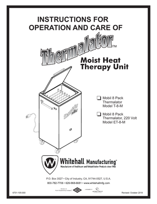
INSTRUCTIONS FOR OPERATION AND CARE OF
Mobil 8 Pack Thermalator Model T-8-M Mobil 8 Pack Thermalator, 220 Volt Model ET-8-M
P.O. Box 3527 • City of Industry, CA, 91744-0527, U.S.A. 800-782-7706 • 626-968-6681 • www.whitehallmfg.com Division of ® Acorn Engineering Company
6701-105-000
Revised: October 2018
!
PLEASE READ THIS ENTIRE BOOKLET BEFORE OPERATING YOUR NEW THERMALATOR
!
Failure to follow these instructions could result in damage to your new heating appliance and/or injury European Union CE Mark The presence of the CE Mark on Whitehall equipment means that it has been designed, tested and certified as complying with all applicable European Union regulations and recommendations.
Waste Electrical and Electronic Equipment (WEEE) This symbol on the product or on its packaging indicates that this product must not be disposed of with regular waste. Instead, it is the user's responsibility to dispose of waste equipment according to the local laws. Separate collection and recycling of the waste equipment at the time of disposal will help conserve natural resources and ensure it is recycled in a manner that protects human health and the environment. For information about where the user can drop off the waste equipment for recycling, please contact your local waste collection authority. See Page 14 for instructions on how to disassemble the equipment for recycling purposes.
Electric Shock The Electric Shock Symbol is used to indicate a hazard arising from dangerous voltage. Any mishandling could result in irreparable damage to the equipment and/or personal injury or death.
General Warning or Caution The Exclamation Symbol appears in Warning and Caution statements. This symbol designates where personal injury or damage to the equipment is possible.
WARNING To avoid electric shock, connect the instrument to properly earth-grounded, GFCI protected, 3-prong receptacles only. Failure to observe this precaution can result in severe injury.
Ÿ
DO NOT operate the appliance without properly filling with water. Under no circumstance should the appliance be operated without water, as operating the appliance without water may result in damage to the heating element. Fill appliance with water to the prescribed level before plugging into an electrical receptacle.
Ÿ
CONNECT the appliance into a properly polarized G.F.C.I. (Ground Fault Circuit Interrupter) electrical receptacle for protection against electrical shock. Have a qualified electrician verify the wall socket is properly polarized and grounded. Use only the power cordset provided with the unit. The Thermalator appliance must be properly grounded.
Ÿ
AVOID skin contact with HOT water at all times! Carefully place thermal packs into the Thermalator to avoid splashing onto skin or coming into contact with HOT water. DO NOT reach into HOT water with bare hands to remove heated thermal packs. Use a grasping device, such as tongs, to remove thermal packs from HOT water.
Ÿ
CAUTION: The enclosure surfaces are hot. Avoid skin contact with the hot surfaces and the cabinet.
Ÿ
PREVENT the power cord or any electrical wires from touching the hot surfaces.
Ÿ
DO NOT use in the presence of flammable liquids or gases, as these may present a fire and/or explosion hazard.
Ÿ
ALWAYS allow the appliance to cool down before draining water or moving unit.
Ÿ
DO NOT use the lid knob to lift or transport appliance. Use the side handles to lift or move.
Ÿ
NEVER leave appliance operating unattended for long periods of time. Water can evaporate and cause appliance to overheat which may result in damage to the heating element. Turn "OFF" when not in use.
a WHITEHALL MANUFACTURING • P.O. BOX 3527 • City of Industry, CA 91744-0527 U.S.A Phone (800) 782-7706 • (626) 968-6681 • Fax (626) 855-4862 • Web: www.whitehallmfg.com
Instructions for Operation and Care of Mobil 8 Pack Thermalator
TABLE OF CONTENTS DESCRIPTION... 2 SET UP INSTRUCTIONS... 3-6 What's included?... 3 Unpacking my Thermalator... 3 Where do I put my Thermalator?... 3 Pre-soaking Thermal Packs... 3 Filling my unit... 4-5 Emptying my unit... 5
USING YOUR THERMALATOR... 6-8 Before the first use... 6-7 How do I use the Thermal Packs?... 7 How do I change the temperature?... 8 How do I use different size Thermal Packs?... 8
MAINTENANCE... 9 CLEANING... 9 STORAGE... 9 TROUBLESHOOTING... 10 TECHNICAL INFORMATION... 11-14 Exploded view (T-8-M)... 11 Replacement parts (T-8-M)... 12 Replacement parts (ET-8-M)... 13 Electrical Parts Disassembly... 14
3 WHITEHALL MANUFACTURING • P.O. BOX 3527 • City of Industry, CA 91744-0527 U.S.A Phone (800) 782-7706 • (626) 968-6681 • Fax (626) 855-4862 • Web: www.whitehallmfg.com
Instructions for Operation and Care of Mobil 8 Pack Thermalator
Congratulations on receiving your Mobil 8 Pack Thermalator. Your Thermalator is a simple and trouble-free unit to operate. The tank body, lid, bottom and tank housing are all made from type 304 stainless steel. The controls are an ON/OFF switch on the front of the unit and a thermostat on the rear to control the water temperature. Unit is preset set to a normal operating temperature. Side handles and a knob on the lid minimize contact with the hot surface. The unit has Thermal Packs with blue and white tabs and a large stainless steel rack adapter that fits onto a stainless steel wire rack. Inside the unit is a heating element and a temperature sensor. Side handles and locking casters below allow easy movement of the unit. A drain valve is located on the back of the unit.
Model T-8-M 100-120 Volts, 50/60 Hz, 15 Amps
Model ET-8-M 200-240 Volts, 50/60 Hz, 6 Amps
Thermal Pack Lid Large Rack Adapter
Blue tabs
Large Wire Rack
Handle
Hospital Grade Power Cord
ON/OFF Switch
Conditions of use: 1. Indoor use only 2. Altitude 2,000 max 3. Ambient temperatures 5ºC to 40ºC 4. Relative humidity maximum 80% for up to 31ºC, maximum 50% for up to 40ºC ambient 5. Mains supply voltage fluctuations up to +/-10% of the rated voltage 6. Mains supply voltage shall be protected against temporary and transient over-voltage per category II requirements 7. Pollution degree 2
2 WHITEHALL MANUFACTURING • P.O. BOX 3527 • City of Industry, CA 91744-0527 U.S.A Phone (800) 782-7706 • (626) 968-6681 • Fax (626) 855-4862 • Web: www.whitehallmfg.com
Instructions for Operation and Care of Mobil 8 Pack Thermalator
OPERATOR SKILLS AND TRAINING Skills:
TRAINING
Operators using the Thermalator need a working knowledge of occupational therapy procedures.
Operator trainees need to:
!
Ÿ be trained in occupational therapy protocols. Ÿ read and understand this manual.
WARNING
Only trained personnel to operate the Thermalator. Untrained operators can cause injury or be injured.
INSPECTING THE THERMALATOR This Whitehall product has been carefully packaged at the factory to minimize the possibility of damage during shipping. - Inspect the packaging for external signs of damage. - Inspect the contents for damage. If there is visible damage to the instrument upon receipt, inform the shipping company and Whitehall immediately.
!
WARNING
Do not attempt to operate this equipment if there is evidence of shipping damage or you suspect the unit is damaged. Damaged equipment may present additional hazards to you. Contact Whitehall technical support for advice before attempting to plug in and operate damaged equipment.
Inspection Checklist Ÿ Is the Thermalator free of excessive wear? Ÿ
Is a properly-grounded and voltage-matched hospital grade receptacle available?
Ÿ Is the outlet equipped with a functioning GFI?
SETTING UP 1. Your new Thermalator includes the following: 1 Thermalator Model T-8-S or ET-8-S 8 Thermal Packs (8 Standard) 1 Wire Rack - Medium, Vinyl Coated 1 Left / 1 Right Rack Adapter (stainless steel) 1 Filler Hose 1 Instructions for Operation and Care If you are missing anything, please call the phone number listed on the back page.
2. Unpacking your Thermalator Remove all the shipping material. Remove Thermal Packs and wire rack from inside the tank. Remove all packaging from inside the tank, especially from under the heating element inside the tank. Clean the unit thoroughly before using.
3. Device Placement For operation, the Thermalator must be placed on a non-flammable, non-combustible surface or material. Avoid operating the unit in close proximity of any such materials.
Avoid operating this unit in close proximity of materials subject to damage from moisture.
4. Pre-Soaking Thermal Packs Presoak thermal packs (Critical, if not presoaked properly, the tank may develop surface rust during use). Inspect the packs for any tears and damaged or loose threads before starting the presoak process. If packs are damaged, do not use. Before the first use, you must condition each Thermal Pack. 1- Take the Thermal Pack by the corner loops - one white and one blue or black - so the sections are horizontal. 2- Gently shake the pack back and forth to evenly distribute the filler material.
Shake to distribute the dry material 3
WHITEHALL MANUFACTURING • P.O. BOX 3527 • City of Industry, CA 91744-0527 U.S.A Phone (800) 782-7706 • (626) 968-6681 • Fax (626) 855-4862 • Web: www.whitehallmfg.com
Instructions for Operation and Care of Mobil 8 Pack Thermalator
3- Place the thermal packs in a large plastic, stainless steel or enamel container (do not use aluminum). DO NOT use the Thermalator for presoaking packs. 4- Fill the container with enough tap water to completely cover the Thermal Packs. 5- Soak the packs for two hours minimum, more is recommended. If the presoak water turns cloudy, change the presoak water and soak packs again. Repeat until water is clear. 6- Turn packs to upright position. The packs are now ready to use.
Turn the packs to upright
The Thermalator is to operate only in ambient temperatures of 5ºC to 40ºC.
FILLING your unit 1 Make sure the unit is unplugged and all packaging has been removed.
2 Check the drain valve before filling. Use the hose provided. Fill unit about 3/4 full with tap water. Ensure that no liquids are spilled into the unit. If conductive materials enter the enclosure, turn off the unit and unplug from power immediately. Contact Whitehall or a licensed technician for service.
3 Place the wire rack inside the unit. Be careful of the heating element.
4 Put the Pre-Soaked Thermal Packs on the wire rack. Place all the blue or white tabs up.
4 WHITEHALL MANUFACTURING • P.O. BOX 3527 • City of Industry, CA 91744-0527 U.S.A Phone (800) 782-7706 • (626) 968-6681 • Fax (626) 855-4862 • Web: www.whitehallmfg.com
3/4
Instructions for Operation and Care of Mobil 8 Pack Thermalator
5 Add more water, if necessary, to cover the Thermal Packs. Uncovered packs may be damaged during heating.
6 Close the lid.
Caution! Lid can pinch fingers.
Caution! Do not attempt to move the unit with water in the unit.
7 Plug the power cord into an AC outlet. A Ground Fault Circuit Interrupter is recommended because it will give additional protection from electric shock.
8 Facing the front of the unit, turn the power switch to the ON position. Indicator light should be illuminated.
AC
EMPTYING your unit 2 Unplug the unit.
1 Facing the front of the unit , turn the power switch OFF. The light will go out.
5 WHITEHALL MANUFACTURING • P.O. BOX 3527 • City of Industry, CA 91744-0527 U.S.A Phone (800) 782-7706 • (626) 968-6681 • Fax (626) 855-4862 • Web: www.whitehallmfg.com
Instructions for Operation and Care of Mobil 8 Pack Thermalator
3 Let the water cool to
4 Attach filler hose to
room temperature. Remove the Thermal Packs and the wire rack.
the drain outlet. Turn handle to release water into a sink or floor drain.
USING the Thermal Pack 1- For each use:
2 Using tongs,
1 Open the lid.
carefully remove the Thermal Pack. Caution: the Thermal Pack can cause skin burns.
3 Wrap the pack in a
4 Put the wrapped
Thermal Pack Cover or 5 to 6 layers of terry toweling.
pack on the area to be treated for a pre-set treatment time.
!
WARNING
Use the Thermalator only as directed in this manual. Any other use can cause injury. 6 WHITEHALL MANUFACTURING • P.O. BOX 3527 • City of Industry, CA 91744-0527 U.S.A Phone (800) 782-7706 • (626) 968-6681 • Fax (626) 855-4862 • Web: www.whitehallmfg.com
Instructions for Operation and Care of Mobil 8 Pack Thermalator
5 Remove the Thermal Pack from the patient.
7 Return the pack to
6 Remove the Thermal Pack Cover or toweling. Hang to dry or launder.
8 Close the lid. The
the Thermalator. If the blue tab was up, put the white tab up now. Work your way from first to last, reversing tabs each time.
Thermal Pack will be reheated within 15 minutes and ready for use.
BLUE
2- Daily use:
1 Add more water, if necessary, to cover the Thermal Packs. Uncovered packs may be damaged during heating.
2 Place all the blue tabs in the same reference (either all up or all down) to start the day.
7 WHITEHALL MANUFACTURING • P.O. BOX 3527 • City of Industry, CA 91744-0527 U.S.A Phone (800) 782-7706 • (626) 968-6681 • Fax (626) 855-4862 • Web: www.whitehallmfg.com
Instructions for Operation and Care of Mobil 8 Pack Thermalator
3- Periodic use: The water temperature for normal operating conditions is about 165°F (74°C). The thermostat is very sensitive; even a small adjustment can raise or lower the temperature several degrees. The thermostat has an adjustable temperature range of 65°F (18°C) to 175°F (79°C) ±5°F (-15°C). To adjust the temperature, you need a Thermometer capable of 180° F (83° C). This product is protected by a High Limit Thermostat which will disconnect power in the event that the unit reaches excessive temperatures. If this condition does occur, have a licensed technician check the unit and reset the thermostat if the cause of overheating is removed.
6 Using the knob, turn clockwise to increase the
5 Facing the back of the unit, find the metal temperature stem between the 2 screws in the lower middle of the unit. Attach knob.
temperature. Allow the temperature to stabilize, and measure the water temperature with the thermometer. CAUTION: Sensitive thermostat - a small adjustment changes several degrees. Temperature range of 65°F (18°C) to 175°F (79°C) ±5°F (-15°C).
TEMPERATURE
USING the Wire Rack Your Thermalator uses many different sizes of Thermal Packs. For Half, Cervical or Myofacial sizes, use the adapter as shown. For Standard, Knee/Shoulder, 10" x 18" and 10" x 24" sizes, turn the adapter over. For oversize, use only the wire rack.
Knee/Shoulder Standard
Cervical Myofacial Half
Large Rack Adapter
10" x 18" 10" x 24"
8 WHITEHALL MANUFACTURING • P.O. BOX 3527 • City of Industry, CA 91744-0527 U.S.A Phone (800) 782-7706 • (626) 968-6681 • Fax (626) 855-4862 • Web: www.whitehallmfg.com
Oversize
Instructions for Operation and Care of Mobil 8 Pack Thermalator
MAINTENANCE
CARE AND CLEANING
The Thermalator design is nearly maintenance-free. It should, under most conditions, give many years of reliable service. Clean and replace the Thermal Packs as described below.
Before cleaning the appliance, be sure to turn power switch "OFF" and unplug the unit from the electrical receptacle. If necessary, empty (drain) the appliance by following instructions as outlined in the "EMPTYING your unit" section.
1. Routine Maintenance (As Needed) •
See Care and Cleaning
Ÿ No bleach or any cleaner with high chlorine content should be used under any circumstance.
•
Always keep the Thermal Packs under water. Replace any water that has evaporated.
Ÿ Clean regularly for optimal service and operation.
•
Destroy or discard any contaminated Thermal Packs.
2. Monthly Maintenance
Ÿ Fill daily with water. Water is constantly lost during operation due to evaporation.
•
See Care and Cleaning
Ÿ Chlorine in regular tap water may be present in high enough concentrations to damage the unit.
•
Clean wire rack and insert using mild soap. Rinse thoroughly with clean tap water. Dry with soft cloth.
Ÿ Inspect the heating element for pitting and other visible damage during regular cleaning intervals.
•
Scrub your Thermal Packs with warm soap and water.
Ÿ Inspect the power cord for wear, fraying, and other visible damage during regular cleaning.
•
Keep the pH (a measure of acidity of the water) between 7.4 and 7.8 to reduce the scaling and residue build-up.
Ÿ Use only appropriate cleaning materials and tools for cleaning the unit. Ensure all cleaning materials are removed before use. It is the responsibility of the user to decontaminate and clean any spillage of hazardous materials before use.
3. Yearly Maintenance •
•
Replace worn out Thermal Packs. When The packs begin to wear out, the non-toxic filler oozes through the fabric and seams. The individual cells seem empty. These packs don't hold the heat. Throw away worn Thermal Packs. Have a professional electrician thoroughly check the following: 1 - Test for leakage current, dielectric strength, and receptacle polarity and ground. If you need test details, call the number listed on the back page. 2 - Check the power cord and plug. They should be free of cuts, abrasion and other damage. Replace the power cord assembly if it is damaged. Use only factory authorized replacement parts. 3 - Remove the bottom cover and check all electrical components and connections. Replace any parts that are in questionable condition. Use only factory authorized replacement parts. There are no user serviceable parts inside the unit. Refer all service and repair to Whitehall or a licensed technician. Do not attempt to take the unit apart, modify or interfere with the components or electrical parts. Doing so is hazardous and voids all warranties.
STORAGE 1. Storing the Thermalator • See Care and Cleaning •
Place the Thermalator upright in a dry area away from any chemicals.
2. Storing the Thermal Packs •
Scrub your Thermal Packs with warm soap and water.
•
Moist and Cold 1 - Put the moist Thermal Pack in a plastic bag. 2 - Seal the bag. 3 - Store the bag in the freezer (recommended) or refrigerator.
•
Dry 1 - Air dry the Thermal Pack completely in a well ventilated area. The filler will become hard and caked. This doesn't hurt the bags; more PreSoaking time is then necessary. 9
WHITEHALL MANUFACTURING • P.O. BOX 3527 • City of Industry, CA 91744-0527 U.S.A Phone (800) 782-7706 • (626) 968-6681 • Fax (626) 855-4862 • Web: www.whitehallmfg.com
Instructions for Operation and Care of Mobil 8 Pack Thermalator
TROUBLESHOOTING Problem
Cause
Solution
Water doesn't get hot, even though unit is plugged in and switch is ON
Circuit breaker is off
Adjust the thermostat
Thermostat is not working
Replace the thermostat
Heating element is burned out
Replace the heating element
The Thermo Packs are worn out (seeping)
Replace the Thermal Packs
Too long between cleaning
Drain, clean and refill
The thermostat is set too high
Adjust the thermostat
The thermostat is broken
Replace the thermostat
Thermal Packs too hot and then too cool
The thermostat is broken
Replace the thermostat
Thermal Packs too cool
The thermostat is set too low
Adjust the thermostat
The thermostat is broken
Replace the thermostat
There is a power failure
Check the circuit and turn on the breaker
Contact with ferrous metal
Remove the ferrous metal item from the unit -usually a staple, paper clip, safety pin, etc. Clean thoroughly.
Water is cloudy
Thermal Packs too hot
Rust in unit
REPAIR OF UNIT It may be necessary or you may desire to return the Thermalator unit for service. In that case, we would appreciate you contacting Whitehall Manufacturing directly. We will make arrangements for the unit to be returned to our production location. When the unit is received by us, an estimate of repairs will be made and you will be contacted. Please- we appreciate warranty repair or any other repair be arranged directly with Whitehall Manufacturing. If you are not satisfied with our service, then and only then, contact your dealer.
10 WHITEHALL MANUFACTURING • P.O. BOX 3527 • City of Industry, CA 91744-0527 U.S.A Phone (800) 782-7706 • (626) 968-6681 • Fax (626) 855-4862 • Web: www.whitehallmfg.com
Instructions for Operation and Care of Mobil 8 Pack Thermalator
Exploded View POWER INLET
DPST SWITCH
FUSE 1
L
1
FUSE 2
2
HEATING ELEMENT
HI TEMP THERMOSTAT 4
N
38
OPERATING THERMOSTAT
5
GND
2
1
36
Use only Time Delay Fuse. See Item 12
3
34
33
37
4
5 6
7 8 32 9
5
10
31
11
35
12 13
30
14
29
Fuse 1
28
15
27
16
26 25
17
Fuse 2
11
18
19
20
19
22
Protective Conductor Terminal The protective conductor terminal symbol in the above figure identifies the location of the bonding terminal, which is bonded to conductive accessible parts of the enclosure for safety purposes.
23
24 Alternating Current Fuse Location
11 WHITEHALL MANUFACTURING • P.O. BOX 3527 • City of Industry, CA 91744-0527 U.S.A Phone (800) 782-7706 • (626) 968-6681 • Fax (626) 855-4862 • Web: www.whitehallmfg.com
Instructions for Operation and Care of Mobil 8 Pack Thermalator
Model T-8-M (120 VAC 60 Hz) ITEM 1 2 3 4 5 6 7 8 9 10 11 12 13 14 15 16 17 18 19 20 21 22 23 24 25 26 27 28 29 30 31 32 33 34 35 36 37 38
PART NUMBER 6502-520-000 0338-004-000 6702-532-199 0126-058-000 6702-151-199 6702-050-002 6505-500-000 0710-446-000 6505-511-000 6702-520-199 0116-010-000 0116-008-000 6505-508-000 6900-136-000 0710-232-000 6505-546-000 6702-518-001 6512-006-000 6507-058-000 0108-103-000 0322-003-000 0308-010-000 0302-011-000 6507-008-000 2803-300-000 0337-003-000 0302-007-000 6700-041-000 0358-003-000 6702-531-199 6505-510-000 0118-001-000 0302-005-000 0331-031-000 6505-056-000 6702-550-001 6702-045-199 6702-560-001
DESCRIPTION 1/4"-20 high crown acorn nut Plastic washer Handle Spacer 1/4"-20 x 1-1/2" phillips screw Handle - Thermalator Thermometer Clamp Assembly Heating Element (120VAC/1000W) w/ washers & nuts Thermal Overheating Sensor Thermostat (65-170 °) w/ washers & nuts Electrical panel #10-32 x 1/2" truss phillips head screw #6-32 x 3/16" phillips screw Thermostat knob Fuse, ceramic 1/4" x 1-1/4" lg 15A 250VAC Fuse holder assembly 1/4" x 1-1/4" lg 10A/15A 250VA Snap-in power inlet Electrical cover assembly Drain valve 3" caster with brake #6-32 x 5/16" phillips screw #6 lock washer #10-32 nylon insert locknut #6-32 SST hex nut 3" caster 3/8"-16 x 1-1/4" hex head cap screw 3/8" lockwasher 3/8"-16 hex nut 7/8" OD x 5/8" ID norprene tubing Hose clamp Inner tank tensioner On/Off switch 1/4-20 UNC x 1/2" carriage bolt stn stl 1/4-20 UNC stn stl hex nut 1/4" Fender washer Power cord 13A, 125V Insert rack assembly, vinyl coated Cervical hot pack rack adapter Insert support loop, vinyl coated
12 WHITEHALL MANUFACTURING • P.O. BOX 3527 • City of Industry, CA 91744-0527 U.S.A Phone (800) 782-7706 • (626) 968-6681 • Fax (626) 855-4862 • Web: www.whitehallmfg.com
Instructions for Operation and Care of Mobil 8 Pack Thermalator
Model ET-8-M (220 VAC 50/60 Hz) ITEM 1 2 3 4 5 6 7 8 9 10 11 12 13 14 15 16 17 18 19 20 21 22 23 24 25 26 27 28 29 30 31 32 33 34 35 36 37 38
PART NUMBER 6502-520-000 0338-004-000 6702-532-199 0126-058-000 6702-151-199 6702-050-002 6505-501-000 0710-446-000 6505-511-000 6702-520-199 0116-010-000 0116-008-000 6505-508-000 0710-202-000 0710-230-001 6505-546-000 6702-518-001 6512-006-000 6507-058-000 0108-103-000 0322-003-000 0308-010-000 0302-011-000 6507-008-000 2803-300-000 0337-003-000 0302-007-000 6700-041-000 0358-003-000 6702-531-199 6505-515-000 0118-001-000 0302-005-000 0331-031-000 Call for part # 6702-550-001 6702-045-199 6702-560-001
DESCRIPTION 1/4"-20 high crown acorn nut Plastic washer Handle Spacer 1/4"-20 x 1-1/2" phillips screw Handle - Thermalator Thermometer Clamp Assembly Heating Element (220VAC/1000W) w/ washers & nuts Thermal Overheating Sensor Thermostat (65-170 °) w/ washers & nuts Electrical panel #10-32 x 1/2" truss phillips head screw #6-32 x 3/16" phillips screw Thermostat knob Fuse, ceramic 5mm x 20mm 6A 250V time delay Fuse holder assembly 5mm x 20mm 10A/15A 250VA Snap-in power inlet Electrical cover assembly Drain valve 3" caster with brake #6-32 x 5/16" phillips screw #6 lock washer #10-32 nylon insert locknut #6-32 SST hex nut 3" caster 3/8"-16 x 1-1/4" hex head cap screw 3/8" lockwasher 3/8"-16 hex nut 7/8" OD x 5/8" ID norprene tubing Hose clamp Inner tank tensioner On/Off switch 1/4-20 UNC x 1/2" carriage bolt stn stl 1/4-20 UNC stn stl hex nut 1/4" fender washer Power cord 13A, 125V Insert rack assembly, vinyl coated Cervical hot pack rack adapter Insert support loop, vinyl coated
13 WHITEHALL MANUFACTURING • P.O. BOX 3527 • City of Industry, CA 91744-0527 U.S.A Phone (800) 782-7706 • (626) 968-6681 • Fax (626) 855-4862 • Web: www.whitehallmfg.com
Instructions for Operation and Care of Mobil 8 Pack Thermalator
ELECTRICAL PARTS DISASSEMBLY
Switch
Thermal Sensor Thermostat Heating Element
Fuses
Fuse Holder
Power Inlet
14 WHITEHALL MANUFACTURING • P.O. BOX 3527 • City of Industry, CA 91744-0527 U.S.A Phone (800) 782-7706 • (626) 968-6681 • Fax (626) 855-4862 • Web: www.whitehallmfg.com
Mailing Address: P.O. Box 3527 • City of Industry, CA 91744-0527 U.S.A Physical Address: 15125 Proctor Avenue • City of Industry, CA 91746 U.S.A Phone 800-782-7706 • 626-968-6681 Fax 626-855-4862 Web: www.whitehallmfg.com E-mail: info@whitehallmfg.com Any questions regarding servicing of products in Europe or the Middle East should be directed to: Acorn Powell, Limited • 5 Brearley Court, Baird Road Quedgeley, Gloucester GL2 2AF, United Kingdom Phone (44) 01452 721211 • Fax (44) 01452 721231 Web www.acornpowell.co.uk technicalsupport@acornpowell.co.uk
MANUFACTURER'S WARRANTY Go to www.whitehallmfg.com to fill out eWarranty Registration, keyword search: WARRANTY. Whitehall Manufacturing Company warrants that its products are free from defects in material or workmanship under normal use and service for a period of one year from date of shipment. Whitehall's liability under this warranty shall be discharged solely by replacement or repair of defective material, provided Whitehall is notified in writing within one year from date of shipment, F.O.B. Industry, California. This warranty does not cover installation or labor charges, and does not apply to materials which have been damaged by other causes such as mishandling or improper care or abnormal use. The repair or replacement of the defective materials shall constitute the sole remedy of the Buyer and the sole remedy of Whitehall under this warranty. Whitehall shall not be liable under any circumstances for incidental, consequential or direct charges caused by defects in the materials, or any delay in the repair or replacement thereof. This warranty is in lieu of all other warranties expressed or implied. Product maintenance instructions are issued with each fixture, and disregard or noncompliance with these instructions will constitute an abnormal use condition and void the warranty. Stainless steel must be properly maintained after the water has been introduced into the fixture, or Whitehall's limited warranty is void. If you have any questions or require technical assistance, please call 800-743-8219. NOTICE TO KEEP ORIGINAL PACKAGING- Regarding warranty claims: customer must retain original packaging for one year upon receipt of product. If packaging is discarded, it is the customer's responsibility to provide adequate packaging. Any shipping claims that are a direct result of customer-provided packaging materials will be handled by the shipper. Member of